


A. Heat Pump Configuration (Steps 3 and 4)
To set the thermostat for heat pump operation,Advanced Setup
Step 3 must be configured to ON. Use the UP and DOWN
ARROW buttons to configure the step. The default is OFF.
Press the mode button to continue to Step 4. Step 4 is used to
set the reversing valve polarity for the heat pump. The vari-
able can be set to either ‘‘B’’or ‘‘O.’’ Set the reversing valve
polarity to the correct valuedepending onthe application.The
default is ‘‘O.’’
NOTE: Step 4 will appear only if Step 3 is set to ON. Step 5
will appear only if Step 3 is set to OFF.
B. Electric Heat Configuration (Step 5)
Step 5 is used to configure the thermostat for electric heat.
The variable can be configured ON or OFF. The default is
OFF.
NOTE: Step 5 will appear only if Step 3 is set to OFF.
C. Deadband (Step 6)
The deadband is the difference in temperature above the cool-
ing set point or below the heating set point that the thermo-
stat will wait before turning on the first stage of heating or
cooling. For example, if the cooling set point is 82 F (28 C)
and the deadband is 2 degrees, the first stage of cooling will
not be energized until the temperature reaches 84 F (30 C).
The range of values is 1 to 6 degrees. The defaultis 2 degrees.
D. Set Point Minimum Difference (Step 7)
The minimum difference between heating and cooling set points
can be user-configured. The range is from 0 to 6 degrees. The
default is 2 degrees. The minimum difference is enforced dur-
ing Autochangeover and Program On operation.
E. Cycles Per Hour Limit (Step 8)
The number of times that heating or cooling can be ener-
gized per hour can be configured. Set the variable to ‘‘d’’ for
no limit. Set the variable to ‘‘d1’’ to disable the 5-minute com-
pressor lockout. The variable can also be set from 2 to 6 cycles
per hour. The default is 6 cycles per hour.
CAUTION:
Damage to compressor could result if
5-minute compressor lockout is disabled or compressor
is allowed unlimited cycles. Do not set thermostat Ad-
vanced Setup Step 8 to ‘‘d’’or ‘‘dl’’unless specifically rec-
ommended for the application.
F. Pre-Occupancy Purge Timer (Step 9)
The pre-occupancy purge allows fresh outside air to be brought
into the space before the Occupied 1 time period. The timer
limits the amount of time that the purge can operate. The
timer can be set from 0 to 3 hours with 15-minute intervals.
The default is 0 hours (disabled).
G. Backlight Display (Step 10)
The display backlight can be set to ON (always on) or OFF
(turn off 8 seconds after usage). The default is ON.
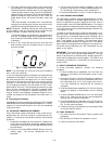
H. Service Filter (Steps 11 and 12)
Step 11 allows the user to reset the Service Filter counter to
zero and remove the ‘‘SERVICE FILTER’’ icon (if displayed
on the thermostat screen). Press the FAN button while in Setup
Step 11 and the counter is reset to zero. Press the Mode but-
ton to adjust the number of hours the blower will run before
the ‘‘SERVICE FILTER’’ icon is displayed. The range is 0 to
1950 hours. Set the variable to 0 to disable this function. The
default is 500 hours.
I. Soft Start (Step 13)
The soft start is used when multiple units are used in an ap-
plication. The soft start staggers the start up times of the
units in the event of power loss and restart. Each unit should
be assigned a unit ID number. The 30-second delay time is
multiplied by the unit ID number to get the total soft start
delay time for each unit. For example, if the unit ID number
is 10, set the Soft Start function to 10, the start-up delay time
is 30 seconds x 10 = 300 seconds (5 minutes). The range is 0
to 99 (ID numbers). A value of 0 disables the function. The
default is 0 (ID number).
J. Farenheit/Celsius Operation (Step 14)
The thermostat can be set to operate in Fahrenheit or Cel-
sius degrees. Set the variable to ‘‘F’’ for Fahrenheit opera-
tion. Set the variable to ‘‘C’’for Celsius operation. The default
is ‘‘F.’’
K. Security Level (Steps 15 to 17)
The Security Level limits the actions that the user can per-
form at the thermostat. There are 4 security levels. When the
security level is set to ‘‘0,’’ no security will be in effect. When
the security level is set to ‘‘1,’’ the set point range is limited
by the settings of Steps 16 and 17. When the security level is
set to ‘‘2,’’ the set point range is limited by the settings of
Steps 16 and 17 and the Program On mode is always in ef-
fect. When the security level is set to ‘‘3,’’ the set point range
is limited by the settings of Steps 16 and 17, the Program On
mode is always in effect, and set point changes are prohib-
ited. The default is 0.
Security Maximum Heat Set Point (Step 16)
If the Security Level is not set to 0, the maximum heating
set point will be in effect. The user will not be allowed to set
the heating set point over the specified value. The range of
values is 35 to 99 F (1 to 37 C). The default is 80 F (27 C).
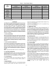
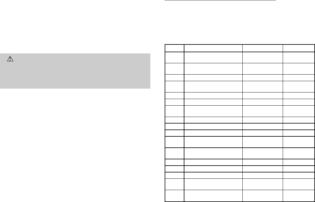
Table 2 — Advanced Setup Configuration
STEP DESCRIPTION RANGE DEFAULT
1* Time of Day
12:00 AM -
11:59 PM
12:00 AM
2* Day of the Week
Sunday through
Saturday
Monday
3 Heat Pump Off/On Off
4
Reversing Valve
Polarity
O/B O
5 Electric Heat Off/On Off
6 Deadband 1 - 6 degrees 2
7
Forced Minimum
Temperature Difference
0 - 6 degrees 2
8 Cycles per Hour d, d1,2-6 6
9 Fan Purge Timer 0:00 - 3:00 0:00
10 Thermoglow™ Backlight Off/On On
11
Reset Service
Filter Icon
——
12
Service Filter
Run Time
0-1950 hrs 500 hrs
13 Soft Start 0 - 99 0
14 Temperature Units F/C F
15 Security Level 0 - 3 0
16
Maximum Allowable
Heat Set Point
35-99F
(1 to 37 C)
80 F (27 C)
17
Minimum Allowable
Cooling Set Point
35-99F
(1 to 37 C)
65 F (18 C)
*Accessed and configured through the Set Clock button.
—4—