


3
INSTALLATION CONSIDERATIONS
Power
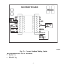
This control is powered by 24VAC only. It requires 24VAC (Rh and/or Rc and C
terminals) of the low−voltage transformer to be connected to it for proper
operation. It will not operate without these 2 connections. Rh and Rc are
connected via PCB breakout jumper. See Fig. 1. For applications using two
24VAC transformers, one in the indoor unit and one in the outdoor unit, connect
the common from each to the C terminal. Connect R from the indoor unit to the
Rh terminal. Connect R from the outdoor unit to the Rc terminal. Then, break
jumper on the circuit board. The W signal is taken from the Rh power and the G
signal is taken from the Rc power. If thermostat has been installed in a
two−transformer application that is later changed to a single−transformer
installation, installer must install a field supplied jumper between Rc and Rh.
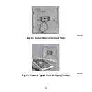
Depending on the installation, up to 14 wires may be required. Installation as
two−piece unit is recommended. Only 2 wires are required for connection
between Display Module and Equipment Control Module. These two wires (V+
and Vg) do not provide ordinary 24VAC. They carry a combination of power
and communications data that is unique to these products.