


I. LOCATE THE UNIT
A. Clearance
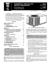
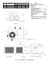
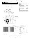
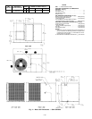
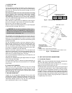
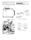
Provide sufficient space for condenser airflow clearance, wir-
ing, and servicing unit. See Fig. 2-4. Locate unit where supply-
and return-air ducts can be conveniently brought out to unit
duct connections.
Unit may be placed with duct side as close to building
as top removal, duct connections, and power connec-
tions permit. Position unit so water or ice from roof does
not drop directly on top of unit or in front of coil. Make pro-
visions for condensate drainage. Maintaina4ftclearance above
unit for vertical air discharge.
Roof installation method for units depends on building con-
struction and special requirements of local building codes.
Be sure that roof can support unit weight.
Maintain clearance around and above unit to provide proper
airflow and service access. See Fig. 2-4.
CAUTION:
Do not restrict condenser airflow. An air
restriction at either the condenser air inlet (the entire
surface of the condenser coil) or the fan discharge can
be detrimental to compressor life.
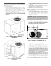
The condenser fan discharges through the top of the unit.
Ensure that the fan discharge does not recirculate to the con-
denser coil. Do not locate the unit either in a corner or under
a complete overhead obstruction, and ensure the following clear-
ances are provided:
On roof overhangs, provide a minimum clearance of 48 in.
above the top of the unit for partial overhangs (such as a
normal house roof overhang). If there is a horizontal exten-
sion on the partial overhang, extension must not exceed
48 inches. For extended overhangs, provide a minimum clear-
ance of 36 in. between unit and overhang.
Provide a minimum clearance of 42 in. for the control box
side next to a block wall or any other grounded surface. Pro-
vide a minimum clearance of 36 in. between the control box
side of the unit and any electrically live parts.
Unit may be installed on wood flooring, or on Class A, B, or C
roof covering materials.
Although unit is weatherproof, guard against water from higher
level runoff and overhangs.
Units should be at least 4 in. above the highest expected wa-
ter, flood, and runoff levels. Do not use the unit if it has been
under water.
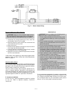
B. Ground-Level Installation
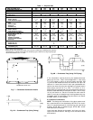
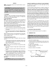
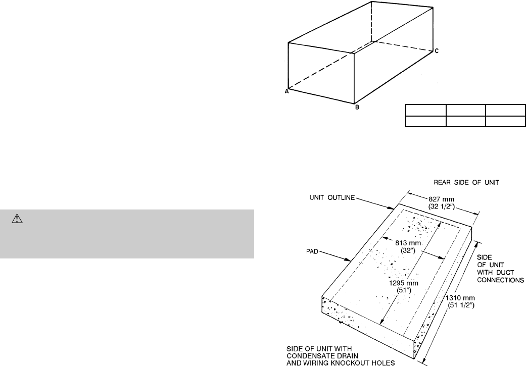
Mount unit on a solid, level pad. See Fig. 5 for unit leveling
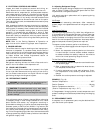
tolerances. Construct pad as shown in Fig. 6. Side of unit with
condensate trap should be flush with pad for proper trap po-
sitioning (see Fig. 2-4). Extend a 24-in. gravel apron around
pad for condensate drainage.
II. RIG AND PLACE UNIT
Inspect unit for transportation damage. File any claim with
transportation agency. Keep upright and do not drop. Level
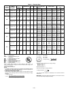
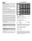
by using unit frame as a reference. See Table 1 for additional
information. Weight is shown in Fig. 2-4. Unit can be moved
with handholds provided in the unit basepan.
III. UNIT DUCT AND FIELD CONNECTIONS
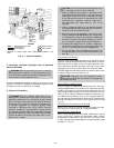
A. Condensate Disposal
NOTE: Ensure that condensate-water disposal methods com-
ply with local codes, restrictions, and practices.
Units remove condensate water through a
3
⁄
4
-in. ID hole lo-
cated on the control box side of the unit.
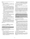
Condensate water can be drained directly onto a gravel apron
in ground-level installations. Install a field-supplied conden-
sate trap at end of condensate connection to ensure proper
drainage. See Fig. 7. Make sure that the outlet of the trap is
at least 1 in. lower than the drain pan condensate connection
to prevent the pan from overflowing. See Fig. 8A and 8B. Prime
the trap with water. When using a gravel apron, make sure
it slopes away from the unit.
MAXIMUM ALLOWABLE
DIFFERENCE (in.)
A-B B-C A-C
1
⁄
4
1
⁄
4
1
⁄
4
Fig. 5 — Unit Leveling Tolerances
NOTES:
1. Extend a 24-in. gravel apron around pad.
2. Provide a 30-in. service clearance at front and rear sides of unit.
Fig. 6 — Pad Dimensions
—5—