


Proceed as follows to inspect and prepare the unit for initial
start-up:
1. Remove all access panels.
2. Read and follow instructions on all WARNING, CAU-
TION, and INFORMATION labels attached to, or shipped
with, unit.
3. Make the following inspections:
a. Inspect for shipping and handling damages such as
broken lines, loose parts, disconnected wires, etc.
b. Inspect for oil at all refrigerant tubing connections
and on unit base. Detecting oil generally indicates a
refrigerant leak. Leak-test all refrigerant tubing con-
nections using electronic leak detector, halide torch,
or liquid-soap solution. If refrigerant leak is de-
tected, see Repairing Refrigerant Leaks section on
page 15.
c. Inspect all field- and factory-wiring connections. Be
sure that connections are completed and tight.
d. Inspect coil fins. If damaged during shipping and han-
dling, carefully straighten fins with a fin comb.
4. Verify the following conditions:
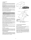
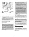
a. Make sure that condenser fan blade is correctly po-
sitioned in fan orifice. Top edge of blade should be
3.125 in. from condenser outlet grille.
b. Make sure that air filter(s) is in place.
c. Make sure that condensate drain pan and trap are
filled with water to ensure proper drainage.
d. Make sure that all tools and miscellaneous loose parts
have been removed.
5. Compressors are internally spring mounted. Do not loosen
or remove compressor holddown bolts.
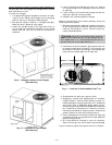
6. Each unit system has 2 Schrader-type ports, one low-
side Schrader fitting located on the suction line, and one
high-side Schrader fitting located on the compressor dis-
charge line. Be sure that caps on the ports are tight.
See Start-Up Checklist in back of book. Unit is now ready for
initial start-up.
START-UP
I. HEATING SECTION START-UP AND ADJUSTMENTS
(For units with accessory electric heaters.)
CAUTION:
Complete the required procedures given
in Pre-Start-Up section on this page before starting unit.
Do not jumper any safety devices when operating the unit.
A. Checking Heating Control Operation
Start and check the unit for proper heating control operation
as follows:
1. Turn on unit electrical supply.
2. Set system switch selector at HEAT position and fan switch
at AUTO. or ON position. Set heating temperature
lever above room temperature.
3. The evaporator fan and first-stage heat will start im-
mediately. If unit is equipped with 2-stage heaters, second-
stage heat will energize upon a call from W2. Check for
heating effect at supply diffusers.
4. After the call for heat has been satisfied, the evaporator
fan will stop. For units equipped with time-delay relay,
evaporator fan will stop after a 30-second time delay.
To shut off unit, set system selector switch at OFF position
or set heating set point lever below room temperature.
B. Heating Sequence of Operation
When power is supplied to unit, transformer (TRAN) is
energized.
With thermostat set to call for heating, sequence of operation
is as follows:
On a call for heat, circuit R-W and R-G are made through
first-stage thermostat bulb. If accessory electric heaters are
used, a relay is energized, bringing on first stage of supple-
mental electric heat and fan. When thermostat is satisfied,
contacts open, deenergizing relay (on all units) and time-
delay relay (on units equipped with time-delay relay). Heat-
ers deenergize, and evaporator fan stops after a 30-second
time delay (on units equipped with time-delay relay).
II. COOLING SECTION START-UP AND ADJUSTMENTS
CAUTION:
Complete the required procedures given
in Pre-Start-Up section, page 11, before starting the unit.
Do not jumper any safety devices when operating the
unit.
Do not operate the compressor when the outdoor tem-
perature is below 40 F (unless accessory low ambient
kit is installed).
Do not rapid-cycle the compressor.
A. Checking Cooling Control Operation
Start and check the unit for proper cooling control operation
as follows:
1. Place room thermostat SYSTEM switch in OFF posi-
tion. Observe that evaporator-fan motor starts when FAN
switch is placed in ON position and shuts down after a
30-second time delay when FAN switch is placed in AUTO.
position.
2. Place SYSTEM switch in COOL position and FAN switch
in AUTO. position. Set cooling control below room tem-
perature. Observe that compressor, condenser fan, and
evaporator-fan motors start. Observe that cooling cycle
shuts down when control setting is satisfied. Evaporator-
fan motor has off-delay (on units equipped with time-
delay relay) of approximately 30 seconds on shutdown.
3. When using an auto. changeover room thermostat, place
both SYSTEM and FAN switches in AUTO. positions.
Observe that unit operates in Heating mode when tem-
perature control is set to ‘‘call for heating’’ (above room
temperature) and operates in Cooling mode when tem-
perature control is set to ‘‘call for cooling’’ (below room
temperature).
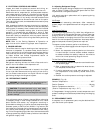
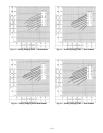
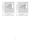
B. Checking and Adjusting Refrigerant Charge
The refrigerant system is fully charged with R-22 refriger-
ant, and is tested and factory-sealed.
NOTE: Adjustment of the refrigerant charge is not required
unless the unit is suspected of not having the proper R-22
charge. See Refrigerant Charge section on page 16 for fur-
ther details.
—12—