


24
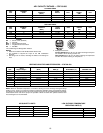
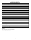
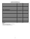
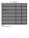
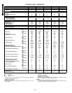
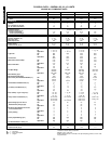
PHYSICAL DATA — 580F036-073
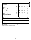
LEGEND
*Evaporator coil fin material/condenser coil fin material. Contact your local repre-
sentative for details about coated fins.
†Weight of 14-in. roof curb.
**Single phase/three-phase.
††Rollout switch lockout is manually reset by interrupting power to unit or reset-
ting thermostat.
***Three-phase standard high heat models have heating input values as shown.
Single-phase standard high heat models have one-stage heating with heating
input values as follows:
580F036 — 115,000 Btuh
580F048,060 — 150,000 Btuh
†††California SCAQMD compliant Low NO
x
models have combustion products
that are controlled to 40 nanograms per joule or less.
NOTES:
1. High-static motor not available on single-phase units.
2. An LP kit is available as an accessory. Kit may be used at elevations as high
as 2000 ft. LP kit is not used with Low NOx units.
UNIT SIZE 580F 036 048 060 072 073
NOMINAL CAPACITY (tons) 34566
OPERATING WEIGHT (lb)
Unit
Al/Cu* 465 476 497 576 626
COMPRESSOR
Type Reciprocating Scroll
Quantity 11111
No. Cylinders (per Circuit) 222NA2
Oil (oz) 50 50 50 54 60
REFRIGERANT TYPE R-22
Expansion Device Acutrol™ Metering Device
Operating Charge (lb-oz)
Circuit 1 (first stage) 4-5 6-6 7-14 9-0 11-0
Circuit 2 (second stage) —————
CONDENSER FAN Propeller Type
Nominal Cfm 3500 4000 4000 4000 4100
Quantity...Diameter (in.) 1...22.0 1...22.0 1...22.0 1...22.0 1...22.0
Motor Hp...Rpm
1
/
4
...1100
1
/
4
...1100
1
/
4
...1100
1
/
4
...1100
1
/
4
...1100
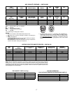
Watts Input (Total) 325 325 325 325 320
CONDENSER COIL
3
/
8
-in. OD Enhanced Copper Tubes, Aluminum Lanced Fins
Rows...Fins/in. 1...17 2...17 2...17 2...17 2...17
Total Face Area (sq ft) 8.36 8.36 10.42 10.42 16.5
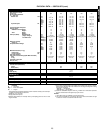
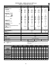
EVAPORATOR FAN Centrifugal Type
Quantity...Size (in.) Std 1...10 x 10 1...10 x 10 1...11 x 10 1...10 x 10 1...10 x 10
Alt 1...10 x 10 1...10 x 10 1...10 x 10 — —
High-Static 1...10 x 10 1...10 x 10 1...10 x 10 1...10 x 10 1...10 x 10
Type Drive Std Direct Direct Direct Belt Belt
Alt Belt Belt Belt — —
High-Static Belt Belt Belt Belt Belt
Nominal Cfm 1200 1600 2000 2400 2100
Maximum Continuous Bhp Std .34 .75 1.20 2.40 2.40
Alt 1.20 1.20 1.30/2.40** — —
High-Static 2.40 2.40 2.90 2.90 2.90
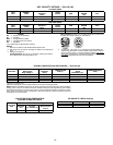
Motor Frame Size Std 48 48 48 56 56
Alt 48 48 56 — —
High-Static 56 56 56 56 56
Nominal Rpm High/Low Std 860/800 1075/970 1075/1040 — —
Alt 1620 1620 1725 — —
High-Static 1725 1725 1725 1725 1725
Fan Rpm Range Std — — — 1070-1460 1070-1460
Alt 685-1045 770-1175 900-1300 — —
High-Static 1075-1455 1075-1455 1300-1685 1300-1685 1300-1685
Motor Bearing Type Ball Ball Ball Ball Ball
Maximum Allowable Rpm 2100 2100 2100 2100 2100
Motor Pulley Pitch Diameter Min/Max (in.) Std — — — 2.8/3.8 2.8/3.8
Alt 1.9/2.9 1.9/2.9 2.8/3.8 — —
High-Static 2.8/3.8 2.8/3.8 3.4/4.4 3.4/4.4 3.4/4.4
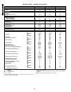
Nominal Motor Shaft Diameter (in.) Std
1
/
2
1
/
2
1
/
2
5
/
8
5
/
8
Alt
1
/
2
1
/
2
5
/
8
——
High-Static
5
/
8
5
/
8
7
/
8
7
/
8
7
/
8
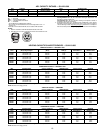
Fan Pulley Pitch Diameter (in.) Std ———4.54.5
Alt 4.5 4.0 5.5 — —
High-Static 4.5 4.5 4.5 4.5 4.5
Belt, Quantity...Type...Length (in.) Std — — — 1...A...39 1...A...39
Alt 1...A...36 1...A...36 1...A...40 — —
High-Static 1...A...39 1...A...39 1...A...40 1...A...40 1...A...40
Pulley Center Line Distance (in.) Std — — — 14.7-15.5 14.7-15.5
Alt 10.0-12.4 10.0-12.4 14.7-15.5 — —
High-Static 10.0-12.4 10.0-12.4 14.7-15.5 14.7-15.5 14.7-15.5
Speed Change per Full Turn of Std — — — 80 80
Movable Pulley Flange (rpm) Alt 48 70 80 — —
High-Static 65 65 60 60 60
Movable Pulley Maximum Full Turns Std ——— 5 5
From Closed Position Alt 555——
High-Static 66555
Factory Setting Std ——— 3 3
Alt 333——
High-Static 3
1
/
2
3
1
/
2
3
1
/
2
3
1
/
2
3
1
/
2
Factory Speed Setting (rpm) Std — — — 1225 1226
Alt 829 932 1100 — —
High-Static 1233 1233 1416 1396 1416
Fan Shaft Diameter at Pulley (in.)
5
/
8
5
/
8
5
/
8
5
/
8
5
/
8
EVAPORATOR COIL
3
/
8
-in. OD Enhanced Copper Tubes, Aluminum Double-Wavy Fins
Rows...Fins/in. 2...15 2...15 3...15 4...15 4...15
Total Face Area (sq ft) 4.17 5.5 5.5 5.5 5.5
Al — Aluminum
Bhp — Brake Horsepower
Cu — Copper
580F036-151