


167
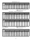
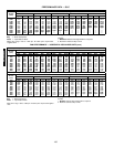
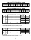
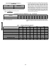
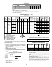
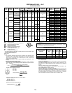
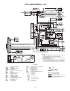
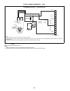
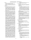
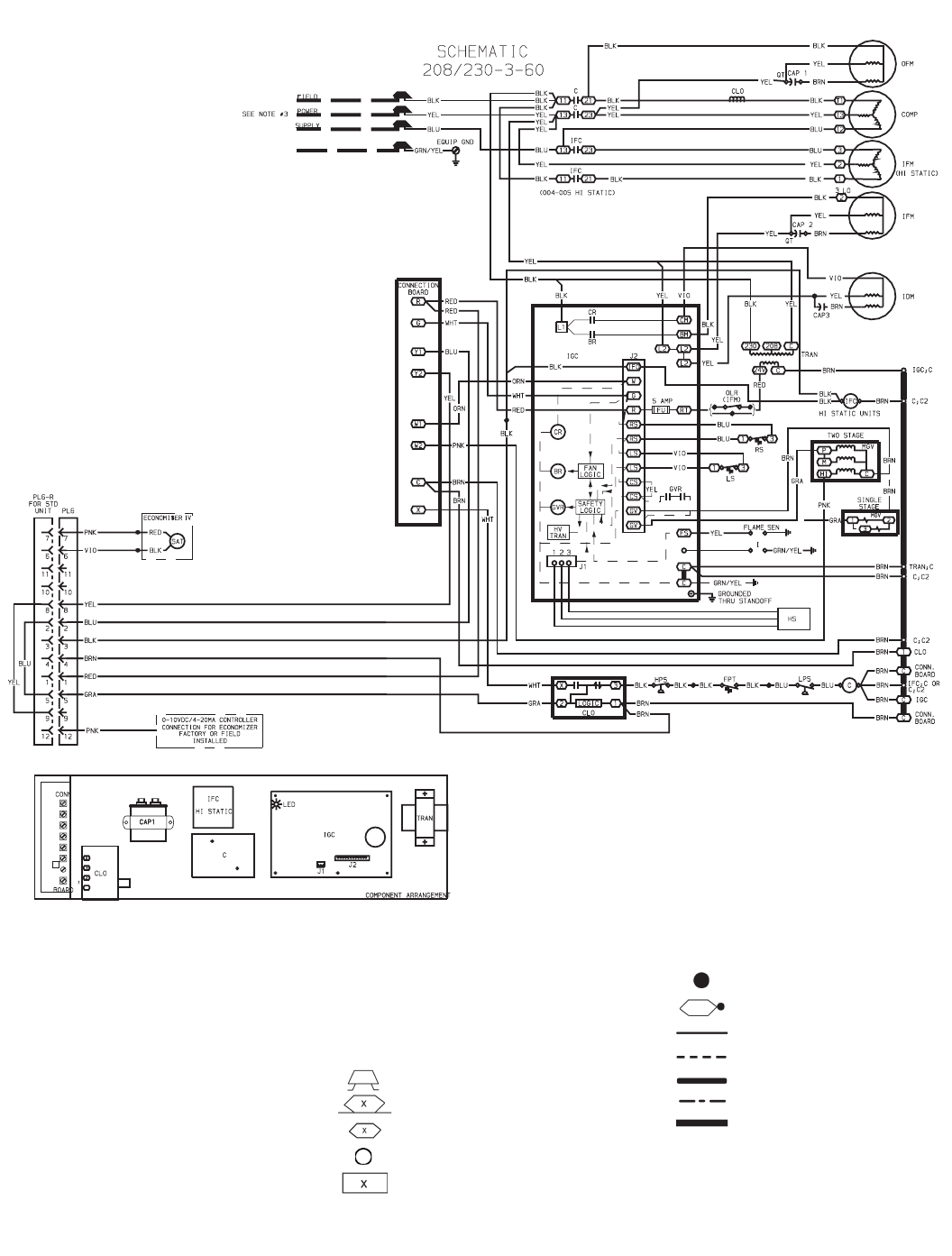
TYPICAL WIRING SCHEMATICS — 581C
LEGEND
OFM — Outdoor (Condenser) Fan Motor
OLR — Overload Relay
P—Plug
PL — Plug Assembly
QT — Quadruple Terminal
RS — Rollout Switch
SAT — Supply Air Temperature Sensor
TRAN — Transformer
Field Splice
Marked Wire
Terminal (Marked)
Terminal (Unmarked)
Terminal Block
C
— Contactor, Compressor
C
AP — Capacitor
C
LO — Compressor Lockout
C
OMP — Compressor Motor
E
QUIP — Equipment
F
PT — Freeze Up Protection Thermostat
F
U—Fuse
G
ND — Ground
H
PS — High-Pressure Switch
H
S—Hall-Effect Sensor
I
— Ignitor
I
DM — Induced-Draft Motor
I
FC — Indoor Fan Contactor
I
FM — Indoor Fan Motor
I
GC — Integrated Gas Unit Controller
L
PS — Low-Pressure Switch
L
S—Limit Switch
MGV — Main Gas Valve
Splice
Splice (Marked)
Factory Wiring
Field Control Wiring
Field Power Wiring
Accessory or Optional Wiring
To indicate common potential only
;
not to represent wiring.
NOTES:
1. If any of the original wire furnished must be replaced, it mus
t
be replaced with type 90 C wire or its equivalent.
2. Three phase motors are protected under primary single
phasing conditions.
3. Use copper conductors only.
4. TRAN is wired for 230 v unit. If unit is to be run with 208 v
power supply, disconnect BLK wire from 230 v tap (ORN
)
and connect to 208 v tap (RED). Insulate end of 230 v tap.