


103
PERFORMANCE DATA (cont)
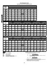
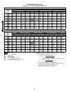
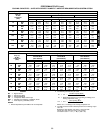
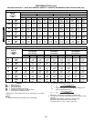
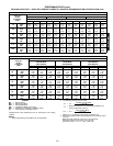
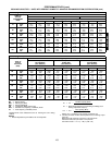
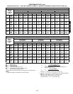
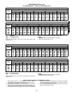
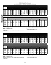
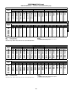
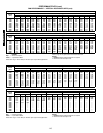
COOLING CAPACITIES — UNITS WITH PERFECT HUMIDITY™ ADAPTIVE DEHUMIDIFICATION SYSTEM OPTION (cont)
LEGEND
*Negative SHC value indicates that the air entering the coil is being
heated.
NOTES:
1. Direct interpolation is permissible. Do not extrapolate.
2. The following formulas may be used:
Where: h
ewb
= Enthalpy of air entering evaporator coil.
3. The SHC is based on 80 F edb temperature of air entering evapo-
rator coil.
Below 80 F edb, subtract (corr factor x cfm) from SHC.
Above 80 F edb, add (corr factor x cfm) to SHC.
Correction Factor = 1.10 x (1 – BF) x (edb – 80).
581B090 (7
1
/
2
TONS) — SUBCOOLING MODE
TEMP (F)
AIR ENT
CONDENSER
(Edb)
AIR ENTERING EVAPORATOR — Cfm/BF
2250/0.10 3000/0.11 3750/0.14
Air Entering Evaporator — Ewb (F)
72 67 62 72 67 62 72 67 62
75
TC 98.4 91.1 81.1 103.7 97.9 91.8 105.8 101.3 94.1
SHC 44.5 55.4 67.0 50.4 65.4 80.5 54.5 72.4 89.5
kW 5.05 4.96 4.87 5.09 5.04 4.97 5.16 5.04 4.99
85
TC 94.2 85.8 76.9 100.3 92.4 85.2 103.5 96.8 89.0
SHC 39.7 51.3 62.7 46.2 58.3 75.7 50.6 68.2 84.3
kW 5.74 5.65 5.55 5.81 5.75 5.64 5.89 5.74 5.70
95
TC 89.9 80.5 72.6 96.9 86.8 78.6 101.1 92.2 83.8
SHC 34.8 47.2 58.3 41.9 51.2 71.0 46.6 63.9 79.1
kW 6.42 6.33 6.22 6.52 6.45 6.31 6.62 6.43 6.40
105
TC 84.6 75.3 68.0 91.6 81.3 73.4 94.5 86.3 78.4
SHC 30.0 42.5 53.9 36.9 49.3 66.4 41.4 59.2 73.8
kW 7.26 7.16 7.05 7.36 7.25 7.15 7.46 7.29 7.23
115
TC 79.2 70.1 63.3 86.2 75.8 68.1 87.9 80.3 72.9
SHC 25.2 37.8 49.4 31.9 47.4 61.9 36.1 54.4 68.5
kW 8.10 7.99 7.87 8.20 8.05 7.98 8.30 8.14 8.05
125
TC 72.8 64.5 57.2 78.0 69.8 62.3 81.6 73.2 69.2
SHC 20.1 33.4 44.1 25.4 42.5 56.5 31.1 48.9 64.7
kW 9.10 8.94 8.83 9.23 9.05 8.95 9.26 9.10 8.99
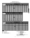
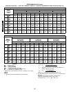
581B090 (7
1
/
2
TONS) — HOT GAS REHEAT MODE*
Temp (F)
Air Ent
Condenser
(Edb)
Air Entering Evaporator — Ewb (F)
75 Dry Bulb
62.5 Wet Bulb
(50% Relative)
75 Dry Bulb
64 Wet Bulb
(55% Relative)
75 Dry Bulb
65.3 Wet Bulb
(60% Relative)
Air Entering Evaporator — Cfm
2250 3000 3750 2250 3000 3750 2250 3000 3750
80
TC 37.74 40.54 42.68 38.48 41.35 43.55 39.12 42.05 44.29
SHC 10.67 15.63 19.63 5.01 9.84 13.74 0.10 4.82 8.63
kW 4.92 4.92 4.92 4.97 4.97 4.97 5.01 5.01 5.01
75
TC 37.34 39.95 41.95 38.08 40.75 42.81 38.72 41.45 43.55
SHC 9.83 14.48 18.24 4.52 9.05 12.70 –0.09 4.34 7.91
kW 5.19 5.19 5.19 5.25 5.25 5.25 5.30 5.30 5.30
70
TC 36.93 39.36 41.22 37.67 40.16 42.07 38.31 40.85 42.80
SHC 8.99 13.33 16.84 4.02 8.26 11.67 –0.28 3.86 7.19
kW 5.46 5.46 5.46 5.52 5.52 5.52 5.58 5.58 5.58
60
TC 36.13 38.18 39.75 36.87 38.97 40.58 37.51 39.66 41.31
SHC 7.31 11.04 14.04 3.04 6.67 9.60 –0.66 2.89 5.75
kW 5.99 5.99 5.99 6.08 6.08 6.08 6.15 6.15 6.15
50
TC 35.32 37.00 38.29 36.06 37.78 39.10 36.75 38.46 39.81
SHC 5.63 8.74 11.25 2.06 5.09 7.53 –1.03 1.93 4.32
kW 6.52 6.52 6.52 6.63 6.63 6.63 6.73 6.73 6.73
40
TC 34.52 35.82 36.82 35.26 36.60 37.62 35.90 37.27 38.32
SHC 3.94 6.44 8.45 1.08 3.51 5.47 –1.41 0.97 2.88
kW 7.05 7.05 7.05 7.18 7.18 7.18 7.30 7.30 7.30
BF — Bypass Factor
Edb — Entering Dry Bulb
Ewb — Entering Wet Bulb
kW — Compressor Motor Power Input
SHC — Sensible Heat Capacity (1000 Btuh) Gross
TC — Total Capacity (1000 Btuh) Gross
t
ldb
=t
edb
–
sensible capacity (Btuh)
1.10 x cfm
t
lwb
= Wet-bulb temperature corresponding to enthalpy of air
leaving evaporator coil (h
lwb
)
h
lwb
=h
ewb
–
total capacity (Btuh)
4.5 x cfm
581B036-150