3
FEATURES/BENEFITS (cont)
Thru-the-Bottom Service Connection
Capability
comes
standard with the rooftop unit to allow power and control wiring
to be routed through the unit’s basepan, thereby minimizing roof
penetrations (to prevent water leaks). Both power and control
connections are made on the same side of the unit to simplify
installation.
The Non-Corrosive, Sloped, Condensate Drain Pan
is
standard and in conformance with ASHRAE (American Society
of Heating, Refrigeration, and Air Conditioning Engineers)
Standard 62 to meet many Indoor Air Quality (IAQ) specifica-
tions. The condensate drain pan offers both bottom and end
drain capability to minimize roof penetrations. The bottom drain
can be used in conjunction with thru-the-bottom connections.
An external trap must be field supplied.
Standard 2-in. Throwaway Filters
are easily accessed
through an easily removable filter access panel located directly
above the air intake hood; no tools are required to change the
filters.
All Units are Designed with a Single Continuous Top Piece
to eliminate leaking at the seams or gasketing, which tends to
deteriorate over time and shift during rigging procedures.
Belt-Driven Evaporator-Fan Motors
allow maximum on-site
flexibility without changing motors or drives.
Low-Voltage Wiring Connections
are easily made due to the
large terminal board which is conveniently located for quick,
simple access.
QUIET, EFFICIENT OPERATION AND DEPENDABLE
PERFORMANCE
All Units are Equipped With Scroll Compressors
which are
fully hermetic with internal vibration isolators for extremely quiet
operation. The scroll compressors are quieter and more reliable
than reciprocating designs. Compressors are mounted on an
independent plate for additional sound integrity and structural
support. Efficient condenser fan and motor design permits
operation at low sound levels.
Totally Enclosed Condenser-Fan Motors
and permanently
lubricated bearings provide additional dependability.
All Coils Use State-of-the-Art Internally Enhanced Copper
Tubing —
Coils are thoroughly tested with helium particles as
well as pressure tested at the factory. Condenser coils have lou-
vered, aluminum lanced fins to provide maximum heat transfer
for optimum efficiency and easy cleaning.
Exclusive Dimpled Heat Exchangers
optimize heat transfer
for improved efficiency. The tubular design permits hot gases to
make multiple passes across the path of the supply air. In addi-
tion, dimpled heat exchanger tubes act as baffles, forcing the
hot gases to stay in close contact with the cell walls to maximize
heat transfer and efficiency.
The California Air Quality Management NOx
requirement of
40 nanograms/joule or less is met with Low kit NOx models in
036-060 sizes.
The Induced Draft Combustion System
eliminates the
unsightly appearance of flue stacks, and diminishes the effects
of winds on heating operation. The inducer fan draws hot com-
bustion gas through the heat exchanger at the optimum rate for
the most effective heat transfer. The induced draft (negative
pressure) also prevents contaminants from entering the supply
air if a leak in the heat exchanger occurs.
The Direct Spark Ignition System
saves operating expense
when compared to old-style pilot ignition systems. No crossover
tube is required, therefore no sooting or pilot fouling problems
can occur.
LP (Liquid Propane) Conversion Kit —
Standard units are
designed for natural gas. An LP Conversion Kit is available as
an accessory, if required. Installation of the accessory LP kit
simply involves changing the gas orifices to accommodate liq-
uid propane gas.
Refrigerant Circuit Protection
assures dependability. All units
have standard:
1) loss-of-charge/low-pressure protection switch which allows
operation at lower ambient conditions while protecting
against low-charge operation
2) freeze-protection thermostat, which protects against evapo-
rator coil frost build-up
3) high-pressure switch, which protects against above normal
operating pressure
4) filter driers, which trap moisture and debris in the refrigera-
tion system.
5) Bryant’s exclusive fixed orifice metering device, which pre-
cisely controls refrigerant flow, preventing slugging and
floodback, while maintaining optimum unit performance by
metering the circuits individually.
Two Independent Compressor Circuits
(all 7
1
/
2
to 12
1
/
2
ton
units) provide pinpoint comfort control, improved efficiency, and
back-up capability.
The Standard Control System
is readily adaptable to all con-
ventional thermostats.
Integrated Gas Unit Controller (IGC) —
All ignition compo-
nents are contained in the compact Integrated Gas Controller
(IGC) that is easily accessible for service. The IGC provides
built in diagnostic capabilities. An LED simplifies troubleshoot-
ing by providing visual fault notification and system status infor-
mation. The IGC board provides exclusive anti-cycle protection
for its gas heat operation. The IGC also contains burner control
logic for dependable heating operation. The LED is visible with-
out removing the unit control box access panel. The 581B units
maximize heating efficiency through the IGC’s control of evapo-
rator fan ON/OFF delays. The IGC helps make 581B units reli-
able for many years.
Patented Cycle-LOC™ Protection System
provides protec-
tion against compressor cycling by monitoring compressor cur-
rent draw. When lack of compressor current exists, the Cycle-
LOC circuit board locks out the compressors. The Cycle-LOC
board may be manually reset by simply switching thermostat to
OFF, and then back to the Cooling or AUTO modes. No manipu-
lation of the unit disconnect switch is needed.
TABLE OF CONTENTS
Page
Features/Benefits. . . . . . . . . . . . . . . . . . . . . . . . . . . . . . . . . .1-4
Model Number Nomenclature . . . . . . . . . . . . . . . . . . . . . . . . . 4
ARI Capacities . . . . . . . . . . . . . . . . . . . . . . . . . . . . . . . . . . . . . 5
Options and Accessories. . . . . . . . . . . . . . . . . . . . . . . . . . . .6-8
Physical Data. . . . . . . . . . . . . . . . . . . . . . . . . . . . . . . . . . . .9-12
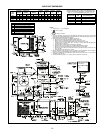
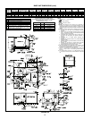
Base Unit Dimensions . . . . . . . . . . . . . . . . . . . . . . . . . . . . 13,14
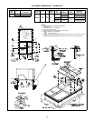
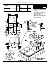
Accessory Dimensions . . . . . . . . . . . . . . . . . . . . . . . . . . . 15,16
Selection Procedure . . . . . . . . . . . . . . . . . . . . . . . . . . . . . . . 17
Performance Data . . . . . . . . . . . . . . . . . . . . . . . . . . . . . . .18-44
Electrical Data . . . . . . . . . . . . . . . . . . . . . . . . . . . . . . . . . .45-48
Application Data. . . . . . . . . . . . . . . . . . . . . . . . . . . . . . . . .49-53
Typical Piping and Wiring. . . . . . . . . . . . . . . . . . . . . . . . . . . . 54
Typical Wiring Schematic. . . . . . . . . . . . . . . . . . . . . . . . . .55-57
Controls . . . . . . . . . . . . . . . . . . . . . . . . . . . . . . . . . . . . . . . 58,59
Guide Specifications . . . . . . . . . . . . . . . . . . . . . . . . . . . . .60-62


