


15
SELECTION PROCEDURE
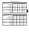
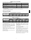
Combination ratings for 569J* units matched with 524J
Series air handlers are in this book. If unit is used with an
air handler, use the Bryant Electronic Catalog AHU
(Air-Handling Unit) selection program to obtain combined
ratings.
I. Determine cooling load, evaporator-air
temperature, and quantity.
Given:
Total Cooling Capacity
Required (TC) 121,000 Btuh...................
Sensible Heat Capacity
Required (SHC) 95,000 Btuh...................
Compressor Type Scroll.........................
Temperature Air Entering
Condenser (Edb) 95_F.........................
Temperature Air Entering
Evaporator (db/wb) 80_F db, 67_Fwb............
Evaporator Air Quantity 4,000 cfm.................
External Static Pressure 0.4 in. wg.................
Length of Interconnecting
Refrigerant Piping 25 ft (Linear).................
Power Supply (V-Ph-Hz) 208/230-3-60.............
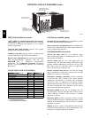
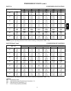
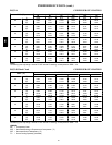
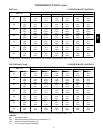
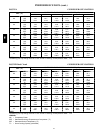
II. Select condensing unit air-handler combination.
For this example, select a 569J*12 matched with a
524J012 coil. This 569J*12/524J12 condensing unit
air-handler combination provides 122,000 Btuh of total
cooling capacity and 97,200 Btuh of sensible capacity at
the given conditions. If other temperatures or airflow
values are required, interpolate the values from the
combination ratings.
III. Determine sizes of liquid and suction lines.
Enter Refrigerant Piping Sizes table. The sizes shown
are based on an equivalent length of pipe. This
equivalent length is equal to the linear length of pipe
indicated at the top of each sizing column, plus a 50%
allowance for fitting losses. (For a more accurate
determination of actual equivalent length in place of
using the estimated 50% value, refer to Bryant System
Design Manual.) For this example, note in the linear
length column that the proper pipe size is
1
/
2
in. for the
liquid line and 1
3
/
8
in. for the suction line.
For extended line lengths over 100 feet, contact your
Bryant representative or application engineer.
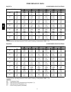
IV. Determine fan rpm and bhp (brake horsepower).
Refer to the 524J Air Handler Catalog -- Fan
Performance table. Enter the Air Handler Fan
Performance table at 524J12 at 4000 cfm and move to
the External Static Pressure (ESP) column. Note that the
conditions require 803 rpm at 1.77 bhp.
V. Determine motor and drive.
Enter the Fan Motor Data tables and find the standard
motor for 524J12 unit rated at 2.4 Hp. Since the bhp
required is 1.77, a standard motor satisfies the
requirement and should be used.
Next, find the type of drive that satisfies the 803 rpm
requirement in the Drive Data tables. For the 524J012
unit, the Standard Drive table shows an rpm range of
666-863. Since the rpm required is 803, the standard
drive satisfies the requirement and should be used.
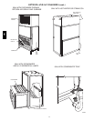
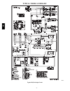
CONTROLS
Operating sequences
When the wall thermostat calls for cooling, terminals G
and Y1 are energized. As a result, the indoor fan contactor
(IFC) and the compressor contactor (C1) are energized,
causing the indoor fan motor (IFM), compressor #1, and
outdoor fans (OFM) to start. The field--supplied and
field--installed liquid line valve also opens, allowing the
system to function in Cooling mode.
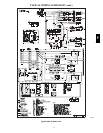
If the unit has 2 stages of cooling, the wall thermostat will
additionally energize Y2. The Y2 signal will energize
compressor contactor #2 (C2), causing compressor #2 to
start.
Regardless of the number of stages, the field--supplied
liquid line valve shall opens and the outdoor fan
motors(OFM) runs continuously while unit is cooling.
When cooling demand decrease, the thermostat will
de--energize Y2. Y2 signal will de--energize compressor
contactor #2 (C2), causing compressor #2 to stop.
When cooling demand has been satisfied, the thermostat
will de--energize Y1, and G terminals. Y1 and G signal
will de--energize compressor contactor #1 (C1), causing
compressor #1 to stop. If the wall thermostat is set to
continuous (CONT), the indoor fan motor will continue
to operate. Otherwise, the indoor fan motor will stop.
The outdoor fan motors (OFM) will turn off and
field--supplied liquid line valve shall close , minimizing
the potential for refrigerant migration.
569J