


B. Filter Drier and Moisture Indicator
The filter drier is factory installed. Moisture indicator is a
field-installed accessory and should be installed just after liq-
uid line shutoff valve. Do not use a receiver. A receiver is not
supplied with the unit and should not be used.
NOTE: Unit is shipped with R-22 holding charge. System pres-
sure must be relieved before removing caps. Recover refrig-
erant prior to brazing.
Pass nitrogen or other inert gas through piping while braz-
ing to prevent formation of copper oxide.
Install field-supplied thermostatic expansion valve(s) in evapo-
rator section. It is recommended that a field supplied liq-
uid line solenoid be positioned in the main liquid line (near
the evaporator coil). It should be wired to close when com-
pressor stops to minimize refrigerant migration during the
‘‘OFF’’ cycle.
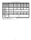
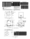
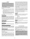
Table 2 — Refrigerant Piping Sizes
LINEAR LENGTH OF PIPING — FT (M)
UNIT
0-25
(0-7.6)
25-50
(7.6-15.2)
50-75
(15.2-22.9)
75-100
(22.9-30.5)
Line Size (in. OD)
LSLSLSLS
569C072
1
⁄
2
1
1
⁄
8
1
⁄
2
1
1
⁄
8
1
⁄
2
1
1
⁄
8
1
⁄
2
1
1
⁄
8
569C090
1
⁄
2
1
1
⁄
8
1
⁄
2
1
1
⁄
8
5
⁄
8
1
1
⁄
8
5
⁄
8
1
3
⁄
8
569C120
5
⁄
8
1
1
⁄
8
5
⁄
8
1
3
⁄
8
5
⁄
8
1
3
⁄
8
5
⁄
8
1
3
⁄
8
576B090
1
⁄
2
1
1
⁄
8
1
⁄
2
1
1
⁄
8
5
⁄
8
1
1
⁄
8
5
⁄
8
1
3
⁄
8
576B102
5
⁄
8
1
1
⁄
8
5
⁄
8
1
1
⁄
8
5
⁄
8
1
3
⁄
8
5
⁄
8
1
3
⁄
8
576B120
5
⁄
8
1
1
⁄
8
5
⁄
8
1
1
⁄
8
5
⁄
8
1
3
⁄
8
5
⁄
8
1
3
⁄
8
LEGEND
L—Liquid Line S—Suction Line
NOTES:
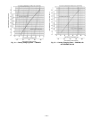
1. Pipe sizes are based on a 2° F (1° C) loss for liquid and suction
lines.
2. Pipe sizes are based on the maximum linear length shown for each
column, plus a 50% allowance for fittings.
3. Charge units with R-22 in accordance with unit installation instructions.
4. Line size conversion to mm is:
in. mm
1
⁄
2
12.7
5
⁄
8
15.9
1
1
⁄
8
28.6
1
3
⁄
8
34.9
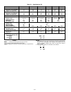
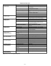
Table 3 — Liquid Line Data
UNIT
MAX
ALLOWABLE
LIQUID LIFT
LIQUID LINE
Max Allowable
Pressure Drop
Max Allowable
Temp Loss
Ft M psi kPa F C
569C072 86 26.2 7 48.3 2 1
569C090 60 18.3 7 48.3 2 1
569C120 70 21.3 7 48.3 2 1
576B090 60 18.3 7 48.3 2 1
576B102 65 19.8 7 48.3 2 1
576B120 65 19.8 7 48.3 2 1
NOTE: Values shown are for units operating at 45 F (7.2 C) saturated
suction and 95 F (35 C) entering air.
V. ELECTRICAL CONNECTIONS
WARNING:
The unit cabinet must have an uninter-
rupted, unbroken electrical ground to minimize the pos-
sibility of personal injury if an electrical fault should
occur. This ground may consist of electrical wire con-
nected to the unit ground lug in the control compart-
ment or conduit approved for electrical ground when
installed in accordance with the NEC and local electri-
cal codes. Failure to adhere to this warning could re-
sult in personal injury.
CAUTION:
Failure to follow these precautions could
result in damage to the unit being installed:
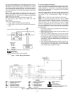
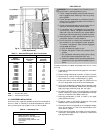
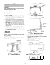
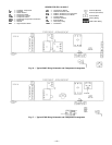
A. Field Power Supply (Fig. 6-8)
1. Make all electrical connections in accordance with NEC
ANSI/NFPA (American National Standards Institute/
National Fire Protection Association) 70, latest edition,
and local electrical codes governing such wiring. Refer
to unit wiring diagram.
2. Use only copper or copper-clad conductor fan connec-
tions between field-supplied electrical disconnect switch
and unit. DO NOT USE ALUMINUM WIRE. Maximum
wire size is no. 2 AWG (American Wire Gage).
3. Voltage to compressor terminals during operation must
be within voltage range indicated on unit nameplate (also
see Table 4). On 3-phase units, voltages between phases
must be balanced within 2% and the current within 10%.
Use the formula shown in Table 4, Note 2, to determine
the percent voltage imbalance. Operation on improper
line voltage or excessive phase imbalance constitutes abuse
and may cause damage to electrical components. Such
operation would invalidate any applicable warranty.
4. Insulate low-voltage wires for highest voltage con-
tained within conduit when low-voltage control wires are
run in same conduit as high-voltage wires.
5. Do not damage internal components when drilling through
any panel to mount electrical hardware, conduit, etc.
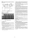
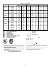
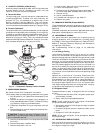
Fig.5—Typical Compressor Mounting (576B Units)
—6—