


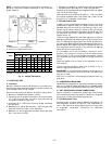
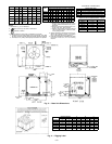
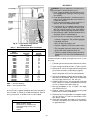
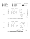


UNIT DIM. A DIM. B DIM. C DIM. D DIM. E DIM. F
569C072
1Ј-6
1
⁄
2
Љ 1Ј-2
3
⁄
4
Љ —1Ј-2
1
⁄
4
Љ 1Ј-4
5
⁄
16
Љ 2Ј-9
5
⁄
16
Љ
[470.0] [375.0] — [362] [415] [846.5]
569C090
1Ј-8Љ 1Ј-6
1
⁄
2
Љ —1Ј-3Љ 2Ј-
5
⁄
16
Љ 3Ј-5
7
⁄
16
Љ
[508.0] [470.0] — [381] [613] [1052.5]
569C120
1Ј-9Љ 1Ј-8Љ 2Ј-0Љ 1Ј-3Љ 2Ј-
5
⁄
16
Љ 3Ј-5
7
⁄
16
Љ
[533.4] [508.0] [609.6] [381] [613] [1052.5]
576B090
1Ј-6Љ 1Ј-4
3
⁄
4
Љ 2Ј-9
13
⁄
16
Љ 1Ј-3Љ 2Ј-
5
⁄
16
Љ 3Ј-5
7
⁄
16
Љ
[457.2] [425.5] [858.8] [381] [613] [1052.5]
576B102
1Ј-7Љ 1Ј-5Љ 2Ј-9
13
⁄
16
Љ 1Ј-3Љ 2Ј-
5
⁄
16
Љ 3Ј-5
7
⁄
16
Љ
[482.6] [431.8] [858.8] [381] [613] [1052.5]
576B120
1Ј-7Љ 1Ј-5Љ 2Ј-9
13
⁄
16
Љ 1Ј-3Љ 2Ј-
5
⁄
16
Љ 3Ј-5
7
⁄
16
Љ
[482.6] [431.8] [858.8] [381] [613] [1052.5]
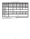
ELECTRICAL CONNECTIONS
CONNECTION SIZES
AA 1
3
⁄
8
Љ DIA [35] FIELD POWER SUPPLY HOLE
BB 2Љ DIA [51] POWER SUPPLY KNOCK-OUT
CC 2
1
⁄
2
Љ DIA [64] POWER SUPPLY KNOCK-OUT
DD
7
⁄
8
Љ DIA [22] FIELD CONTROL WIRING HOLE
SERVICE VALVE CONNECTIONS — 60 Hz
UNIT SUCTION LIQUID
569C072 1
1
⁄
8
Љ [28.6]
1
⁄
2
Љ [12.7]
569C090 1
1
⁄
8
Љ [28.6]
1
⁄
2
Љ [12.7]
569C120 1
1
⁄
8
Љ [28.6]
5
⁄
8
Љ [15.9]
576B090 1
1
⁄
8
Љ [28.6]
1
⁄
2
Љ [12.7]
576B102 1
1
⁄
8
Љ [28.6]
5
⁄
8
Љ [15.9]
576B120 1
1
⁄
8
Љ [28.6]
5
⁄
8
Љ [15.9]
NOTES:
1. Dimensions in [ ] are in millimeters.
2. Center of Gravity. See chart for dimensions.
3. Direction of Airflow.
4. Minimum clearance (local codes or jurisdiction may prevail):
a. Condenser coil, for proper airflow, 36 in. [914] one side, 12 in. [305]
the other. The leftor rearside getting thegreater clearance isoptional.
b. Overhead, 60 in. [1524] to assure proper condenser fan operation.
c. Between units,control box side, 42 in.[1067]
per NEC (National Electrical Code) (U.S.A.
Standard).
d. Between unitand ungrounded surfaces, con-
trol box side, 36 in. [914] per NEC.
e. Between unit and blockor concrete wallsand
other grounded surfaces, control box side,
42 in. [1067] per NEC.
5. With the exception of theclearance for the con-
denser coil as stated in note 4b, a removable
fence or barricade requires no clearance.
6. Unitsmay beinstalled on combustiblefloors made
from wood or Class A, B, or C roof covering
material.
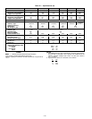
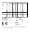
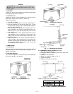
UNIT
WEIGHT CHART*
Std Unit Corner W Corner X Corner Y Corner Z
Lb Kg Lb Kg Lb Kg Lb Kg Lb Kg
569C072 340 154 86 39 53 24 77 35 124 56
569C090 370 168 86 39 78 35 99 45 107 49
569C120 395 179 89 40 92 42 109 49 105 48
576B090 510 231 115 52 89 40 133 60 173 87
576B102 564 256 133 60 97 44 141 64 193 88
576B120 564 256 133 60 97 44 141 64 193 88
*Weights are for aluminum coils.
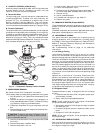
Fig. 3 — Base Unit Dimensions
UNIT
RIGGING WEIGHT* A B C
lb kg in. mm in. mm in. mm
569C072 390 176 45.0 1143 38.5 978 35.5 904
569C090 420 191 45.0 1143 38.5 978 43.5 1105
569C120 445 202 45.0 1143 38.5 978 43.5 1105
576B090 560 254 45.0 1143 38.5 978 43.5 1105
576B102 614 279 45.0 1143 38.5 978 43.5 1105
576B120 614 279 45.0 1143 38.5 978 43.5 1105
*Weights are for aluminum coils.
Fig. 4 — Rigging Label
—5—