


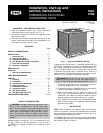
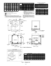
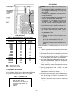


NOTE: If vibration isolators are required for a particular in-
stallation, use corner weight information in Fig. 2 to make
proper selection.
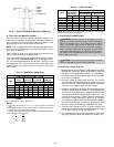
I. LOCATE THE UNIT
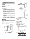
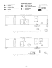
A. Clearance
Maintain clearance around and above unit to provide mini-
mum distance from combustible materials, proper airflow, and
service access. Refer to Fig. 2 and 3.
Minimum clearance (local codes or jurisdiction may prevail):
a. Bottom to combustible surfaces 0 inches.
b. Condenser coil, for proper airflow, 36 in. (914 mm) one side,
12 in. (305 mm) the other. The left or rear side receiving
the greater clearance is optional.
c. Overhead, 60 in. (1524 mm) to ensure proper condenser
fan operation.
d. Between units, control box side, 42 in. (1067 mm) per NEC
(National Electrical Code, U.S.A. Standard).
e. Between unit and ungrounded surfaces, control box side,
36 in. (914 mm) per NEC.
f. Between unit and block or concrete walls and other grounded
surfaces, control box side, 42 in. (1067 mm) per NEC.
Although unit is weatherproof, guard against water from higher
level runoff and overhangs.
Slab-mounted units should be at least 4 in. (102 mm) above
the highest expected water level (flood and runoff). Do not
use the unit if it has been under water.
II. RIG AND PLACE UNIT
Inspect unit for transportation damage. File any claim with
transportation agency. Keep unit upright and do not drop.
Spreader bars are not required if top crating is left on unit.
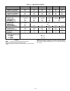
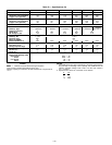
Rollers may be used to move unit across a roof. Level by us-
ing unit frame as a reference. See Tables 1A and 1B and Fig. 4
for additional information. Operating weight is shown in
Tables 1A and 1B.
These units are designed for overhead rigging only. Rig with
packaging assembly and wood bumper strips in place to pre-
vent unit damage by rigging cable. As further protection for
coil faces, plywood sheets may be placed against sides of unit,
behind cables. Run cables to a central suspension point so
that angle from the horizontal is not less than 45 degrees.
Raise and set unit down carefully.
If it is necessary to roll unit into position, mount unit on lon-
gitudinal rails, using a minimum of 3 rollers. Apply force to
rails, not unit. If unit is to be skidded into position, place it
on a large pad and drag it by the pad. Do not apply any force
to unit.
Raise from above to lift unit from rails or pad when unit is in
final position.
Lifting holes are provided in base rails as shown in Fig. 4.
Refer to rigging instructions on unit.
IMPORTANT: If unit has forklift protection skids, be sure to
remove forklift protection skids from under unit before set-
ting unit in place.
After unit is in position, remove shipping materials and rig-
ging skids.
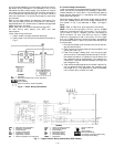
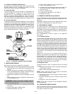
III. COMPRESSOR MOUNTING
Compressors are shipped from the factory held down by 4 bolts.
After unit is installed, loosen each bolt until the snubber washer
can be moved with finger pressure (376B units only). See Fig. 5.
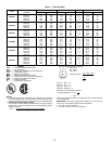
IV. UNIT REFRIGERANT PIPING CONNECTIONS
Suction connection is sweat with plastic cap; liquid connec-
tion is sweat with plastic cap. Refer to Table 2 for refrigerant
piping sizes. Follow standard piping practices.
A. Size Refrigerant Lines
Consider length of piping required between condensing unit
and evaporator, amount of liquid lift, and compressor oil
return. See Table 3 for design details and line sizing. Refer
to evaporator installation instructions for additional
information.
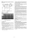
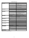
NOTES:
1. Dimensions in [ ] are in millimeters.
2. See Fig. 3 for additional information.
UNIT
WEIGHT CHART*
Std Unit
Corner
W
Corner
X
Corner
Y
Corner
Z
Lb Kg Lb Kg Lb Kg Lb Kg Lb Kg
569C072 340 154 86 39 53 24 77 35 124 56
569C090 370 168 86 39 78 35 99 45 107 49
569C120 395 179 89 40 92 42 109 49 105 48
576B090 510 231 115 52 89 40 133 60 173 87
576B102 564 256 133 50 97 44 141 64 193 88
576B120 564 256 133 60 97 44 141 64 193 88
*Weights are for aluminum coils.
Fig.2—Weight Distribution
—2—