


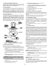


IV. CAPACITY CONTROL (576B120 Only)
A suction pressure-actuated unloader controls 2 cylinders and
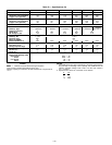
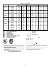
provides capacity control. Unloaders are factory set (see
Table 1A or 1B), but may be field adjusted:
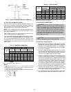
A. Control Set Point
The control set point (cylinder load point) is adjustable from
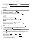
0 to 85 psig (586 kPa). To adjust, turn control set point ad-
justment nut (Fig. 13) clockwise to its bottom stop. In this
position, set point is 85 psig (586 kPa). Then, turn adjust-
ment counterclockwise to desired control set point. Every full
turn counterclockwise decreases set point by 7.5 psig (51.7 kPa).
B. Pressure Differential
The pressure differential (difference between cylinder load and
unload points) is adjustable from 6 to 22 psig (41.4 to 152 kPa).
To adjust, turn pressure differential adjustment screw (Fig. 13)
counterclockwise to its back stop position. In this position,
differential is 6 psig (41.4 kPa). Then, turn adjustment screw
clockwise to desired pressure differential. Every full turn clock-
wise increases differential by 1.5 psig (10.3 kPa).
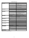
V. COMPRESSOR REMOVAL
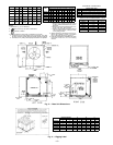
See Tables 1A and 1B for compressor information.
Follow safety codes and wear safety glasses and work gloves.
1. Shut off power to unit. Remove unit access panel (front
of unit).
2. Remove refrigerant from system using refrigerant re-
moval methods described in GTAC II, Module 5, Charg-
ing, Recovery, Recycling, and Reclamation.
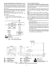
3. Disconnect compressor wiring at compressor terminal
box.
4. Remove bolts from suction flange and discharge serv-
ice valve (576B Units).
CAUTION:
Excessive movement of copper lines at
compressor may cause higher levels of vibration when
unit is restored to service.
5. Remove crankcase heater from compressor base (576B
units only).
6. Remove compressor holddown bolts.
7. Remove compressor from unit.
8. Clean system. Add new liquid line filter drier.
9. Install new compressor in unit.
10. Connect suction and discharge lines to compressor. En-
sure that compressor holddown bolts are in place.
11. Connect wiring.
12. Install crankcase heater.
13. Evacuate and recharge unit, per Step VII.
14. Restore unit power.
VI. CRANKCASE HEATER (Except 569C072)
The crankcase heater prevents refrigerant migration and com-
pressor oil dilution during shutdown when compressor is not
operating.
Close both compressor service valves if applicable when crank-
case heater is deenergized for more than 6 hours.
VII. REFRIGERANT CHARGE
Unit panels must be in place when unit is operating during
charging procedure. Unit is shipped with a holding charge
only. Weigh in 7 lbs (3 kg) of R-22 to start unit. Refer to GTAC II,
Module 5, Charging, Recovery, Recycling, and Reclamation
for additional information.
See Troubleshooting Guide on page 14 for additional
information.
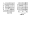
A. Low Charge Cooling
Using Cooling Charging Charts, Fig. 14 and 15, vary refrig-
erant until the conditions of the appropriate chart are met.
Note the charging charts are different from type normally used.
The charts are based on charging the units to the correct sub-
cooling for the various operating conditions. Accurate pres-
sure gage and temperature sensing device are required. Con-
nect the pressure gage to the service port on the liquid line
service valve. Mount the temperature sensing device on the
liquid line, close the liquid line service valve, and insulate it
so that outdoor ambient temperature does not affect the read-
ing. Indoor-air cfm must be within the normal operating range
of the unit.
Operate unit a minimum of 15 minutes. Ensure that tem-
perature and pressure have stabilized. Plot liquid pressure
and temperature on chart and add or reduce charge as re-
quired. Do not vent refrigerant to the atmosphere. Recover
any excess charge. Operate the unit until the system stabi-
lizes. Adjust charge to conform with charging chart, using liq-
uid pressure and temperature to read chart.
B. Refrigerant Leaks
Proceed as follows to repair a refrigerant leak and to charge
the unit:
1. Locate the leak and ensure that refrigerant system pres-
sure has been relieved.
2. Repair leak following accepted practices.
NOTE: Install a new filter drier in the liquid line whenever
the system has been opened for repair.
3. Add a small charge of R-22 refrigerant vapor to system
and leak-test unit.
4. Evacuate refrigerant system if additional leaks are not
found.
5. Charge unit with R-22 refrigerant.
NOTE: Do not vent refrigerant to the atmosphere. Recover
any excess charge.
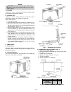
VIII. REFRIGERANT SERVICE PORTS
Each unit has 3 service ports: one on the suction line, one on
the liquid line, and one on the compressor discharge line. Be
sure caps on the ports are tight.
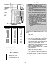
Fig. 13 — Compressor Capacity Control Unloader
—12—