


NOTE: Install branch circuit disconnect of adequate size per
NEC to handle unit starting current. Locate disconnect within sight
from and readily accessible from unit, per Section 440-14 of NEC.
A. ROUTE GROUND AND POWER WIRES
Remove access panel to gain access to unit wiring. Extend wires
from disconnect through power wiring hole provided and into unit
control box.
WARNING: The unit cabinet must have an uninter-
rupted or unbroken ground to minimize personal injury if
an electrical fault should occur. The ground may consist
of electrical wire or metal conduit when installed in
accordance with existing electrical codes. Failure to
follow this warning can result in an electric shock, fire, or
death.
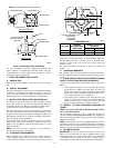
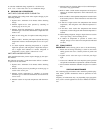
B. CONNECT GROUND AND POWER WIRES
Connect ground wire to ground connection in control box for
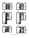
safety. Connect power wiring to contactor as shown in Fig. 9.
C. CONNECT CONTROL WIRING
Route 24-v control wires through control wiring grommet and
connect leads to control wiring. (See Fig. 10.)
Use No. 18 AWG color-coded, insulated (35°C minimum) wire. If
thermostat is located more than 100 ft from unit, as measured
along the control voltage wires, use No. 16 AWG color-coded wire
to avoid excessive voltage drop.
All wiring must be NEC Class 1 and must be separated from
incoming power leads.
Use furnace transformer, fan coil transformer, or accessory trans-
former for control power, 24-v/40-va minimum.
NOTE: Use of available 24-v accessories may exceed the mini-
mum 40-va power requirement. Determine total transformer load-
ing and increase the transformer capacity or split the load with an
accessory transformer as required.
IX. COMPRESSOR CRANKCASE HEATER
When equipped with a crankcase heater, furnish power to heater a
minimum of 24 hr before starting unit. To furnish power to heater
only, set thermostat to OFF and close electrical disconnect to
outdoor unit.
A crankcase heater is required if refrigerant tubing is longer than
50 ft. Refer to the Application Guideline and Service Manual—Air
Conditioner with Puron® Refrigerant.
X. INSTALL ELECTRICAL ACCESSORIES
Refer to the individual instructions packaged with kits or acces-
sories when installing.
XI. START-UP
CAUTION: To prevent compressor damage or personal
injury, observe the following:
• Do not overcharge system with refrigerant.
• Do not operate unit in a vacuum or at negative pressure.
• Do not disable low-pressure switch.
In scroll compressor applications:
• Dome temperatures may be hot.
CAUTION: To prevent personal injury wear safety
glasses, protective clothing, and gloves when handling
refrigerant and observe the following:
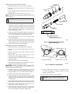
• Back seating service valves are not equipped with
Schrader valves. Fully back seat (counter clockwise)
valve stem before removing gage port cap.
• Front seating service valves are equipped with Schrader
valves.
CAUTION: Do not vent refrigerant to atmosphere. Re-
cover during system repair or final unit disposal.
Follow these steps to properly start up the system:
1. After system is evacuated, fully back seat (open) liquid and
vapor service valves.
2. Unit is shipped with valve stem(s) front seated (closed) and
caps installed. Replace stem caps after system is opened to
refrigerant flow (back seated). Replace caps finger-tight and
tighten with wrench an additional 1/12 turn.
3. Close electrical disconnects to energize system.
4. Set room thermostat at desired temperature. Be sure set
point is below indoor ambient temperature.
5. Set room thermostat to COOL and fan control to ON or
AUTO mode, as desired. Operate unit for 15 minutes.
Check system refrigerant charge.
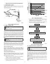
A. SEQUENCE OF OPERATION
Turn on power to indoor and outdoor units. Transformer is
energized.
On a call for cooling, thermostat makes circuits R-Y and R-G.
Circuit R-Y energizes contactor, starting outdoor fan motor and
compressor circuit. R-G energizes indoor unit blower relay,
starting indoor blower motor on high speed.
When thermostat is satisfied, its contacts open, de-energizing
contactor and blower relay. Compressor and motors stop.
If indoor unit is equipped with a time-delay relay circuit, the
indoor blower will run an additional 90 sec to increase system
efficiency.
XII. CHECK CHARGE
A. UNIT CHARGE
Factory charge and charging method are shown on unit informa-
tion plate. Puron® refrigerant cylinders contain a dip tube
which allows liquid refrigerant to flow from cylinder in
upright position. Charge Puron® units with cylinder in upright
position and a commercial-type metering device in manifold hose.
Charge refrigerant into suction line.
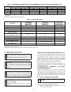
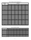
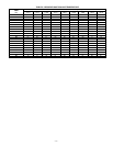
NOTE: Charge must be adjusted in accordance with unit rating
plate, ± 0.6 oz/ft of 3/8-in. liquid line above or below 15 ft,
respectively.
EXAMPLE:
Fig. 9—Line Power Connections
A91056
DISCONNECT
PER N. E. C. AND/OR
LOCAL CODES
CONTACTOR
GROUND
LUG
FIELD GROUND
WIRING
FIELD POWER
WIRING
—6—
→
→