


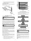

INSTALLING TXV IN PLACE OF PISTON
1. Pump system down to 2 psig and recover refrigerant.
2. Remove hex nut from piston body. Use backup wrench on
fan coils.
3. Remove and discard factory-installed piston. Be sure teflon
seal is in place.
4. Reinstall hex nut. Finger tighten nut plus 1/2 turn.
NOTE: If the piston is not removed from the body, TXV will not
function properly.
CAUTION: To prevent damage to the unit, use a brazing
shield and wrap TXV with wet cloth or use heat sink
material.
5. Install TXV on indoor coil liquid line. Sweat swivel adapter
to inlet of indoor coil and attach to TXV outlet. Use backup
wrench to avoid damage to tubing or valve. Sweat inlet of
TXV, marked “IN” to liquid line. Avoid excessive heat
which could damage valve.
6. Install vapor elbow with equalizer adapter to suction tube of
line set and suction connection to indoor coil. Adapter has
a 1/4-in. male connector for attaching equalizer tube.
7. Connect equalizer tube of TXV to 1/4-in. equalizer fitting
on vapor line adapter.
8. Attach TXV bulb to horizontal section of suction line using
clamps provided. Insulate bulb with field-supplied insula-
tion tape. See Fig. 5 for correct positioning of sensing bulb.
9. Proceed with remainder of unit installation.
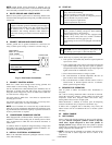
REPLACING TXV ON R-22 INDOOR COIL
1. Pump system down to 2 psig and recover refrigerant.
2. Remove coil access panel and fitting panel from front of
cabinet.
3. Remove TXV support clamp using a 5/16-in. nut driver.
Save the clamp.
4. Remove R-22 TXV using a backup wrench on flare
connections to prevent damage to tubing.
5. Using wire cutters, cut equalizer tube off flush with vapor
tube inside cabinet.
6. Remove bulb from vapor tube inside cabinet.
7. Braze equalizer stub-tube closed. Use protective barrier as
necessary to prevent damage to drain pan.
IMPORTANT: Route the equalizer tube of Puron® TXV
through suction line connection opening in fitting panel prior to
replacing fitting panel around tubing.
8. Install TXV with 3/8-in. copper tubing through small hole
in service panel. Use wrench and backup wrench, to avoid
damage to tubing or valve, to attach TXV to distributor.
9. Reinstall TXV support clamp (removed in item 3).
10. Attach TXV bulb to vapor tube inside cabinet, in same
location as original was when removed, using supplied bulb
clamps (nylon or copper). See Fig. 5 for correct positioning
of sensing bulb.
11. Route equalizer tube through suction connection opening
(large hole) in fitting panel and install fitting panel in place.
12. Sweat inlet of TXV, marked “IN” to liquid line. Avoid
excessive heat which could damage valve.
13. Install vapor elbow with equalizer adapter to vapor line of
line set and vapor connection to indoor coil. Adapter has a
1/4-in. male connector for attaching equalizer tube.
14. Connect equalizer tube of TXV to 1/4-in. equalizer fitting
on vapor line adapter. Use backup wrench to prevent
damage to equalizer fitting.
15. Proceed with remainder of unit installation.
CAUTION: Remove indoor coil piston if unit is to be
installed on system with a TXV metering device.
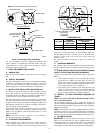
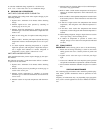
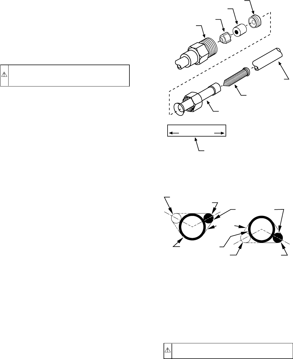
Fig. 4—Check-Flo-Rater® Components
(550A, 552A Only)
A01019
PISTON
RETAINER
PISTON
RING
PISTON
PISTON
BODY
FLARE
ADAPTER
STRAINER
FIELD
CONNECTION
LIQUID LINE STRAINER
APPROX 2” LONG
STRAINER LABEL
(AFFIX TO LIQ. LINE
NEAR STRAINER LOCATION
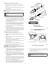
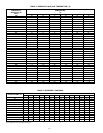
Fig. 5—Position of Sensing Bulb
A81032
2 O'CLOCK
10 O'CLOCK
SENSING BULB
STRAP
SUCTION TUBE
8 O'CLOCK
4 O'CLOCK
7
⁄
8
IN. OD & SMALLER
LARGER THAN
7
⁄
8
IN. OD
—3—