


3
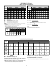
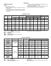
PHYSICAL DATA
LEGEND
*Shipping weights include base unit plus packaging.
†If components are to be split, additional refrigerant will be needed.
**Use Type L copper only.
NOTE:
If components are to be split, the maximum length of refrigerant tubing to be
used is 50 equivalent ft, assuming components will be installed in same horizontal plane.
If components are not to be installed in same horizontal plane, contact your Bryant rep-
resentative for more information.
UNIT 502A
024 036 048 060
SHIPPING WEIGHT (lb)*
560 590 690 700
OPERATING WEIGHT (lb)
Base Unit
450 480 580 590
REFRIGERANT TYPE
R-22
Operating Charge (lb)†
5.4 5.5 8.0 7.6
COMPRESSOR — TYPE
Scroll
Quantity...Model
(1)...ZR23 (1)...ZR34 (1)...ZR49 (1)...ZR57
Oil (oz)
24 42 48 54
HPS Setting (psig)
Cutout
426 ± 7
Reset
320 ± 20
LPS Setting (psig)
Cutout
27 ± 4
Reset
67 ± 7
CONDENSATE DRAIN CONNECTION
Size (in.)...Type
3
/
4
...FPT
CONDENSER FAN
Centrifugal — Direct Drive Centrifugal — Belt Drive
Nominal Cfm
1350 1350 2250 2450
Maximum Rpm
1100 1500
Blower Size (in.)
12 x 6 12 x 9
Pulley Pitch Diameter (in.)
Blower
None 5.0 6.0 6.0
Motor (Variable)
None 2.4-3.4 1.9-2.9 2.4-3.4
Motor Hp
1
/
2
3
/
4
11
1
/
2
Motor Rpm
825 1725 1725 1725
EVAPORATOR AIR FAN (Standard)
Centrifugal — Direct Drive
Nominal Cfm
800 1200 1600 2000
Max Rpm
1100 1150 1050
Blower Size (in.)
10 x 5 10 x 6 10 x 6
Motor Hp (Rpm)
1
/
6
(850)
1
/
2
(1075)
3
/
4
(1050)
EVAPORATOR AIR FAN (Optional)
Centrifugal Belt Drive
Nominal Cfm
Not
Available
1600 2000
Max Rpm
1300
Blower Size (in.)
10 x 8
Motor Hp
1
1
/
2
Motor Rpm
1725
Pulley Pitch Diameter (in.)
Blower
4.2
Motor (Variable)
2.4-3.4
CONDENSER COIL
Copper Tubes — Aluminum Fins
Size (L x H) (in.)
40 x 15 40 x 16 40 x 22
Number of Rows...Fins/in.
4...13.6 4...17 4...13.6
EVAPORATOR COIL
Copper Tubes — Aluminum Fins
Size (L x H) (in.)
34 x 15 34 x 16 34 x 22
Number of Rows...Fins/in.
4...14.4 4...15 4...14.4
INDOOR-AIR FILTERS
Factory-Supplied Cleanable Type
Number...Size (in.)
1...14 x 34 x 1 1...21 x 34 x 1
INTERCONNECTING TUBING SIZE (in.)**
Hot Gas
1
/
2
1
/
2
1
/
2
1
/
2
Liquid
3
/
8
3
/
8
3
/
8
3
/
8
HPS —
High-Pressure Switch
LPS —
Low-Pressure Switch
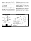
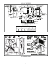
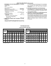
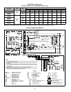
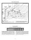
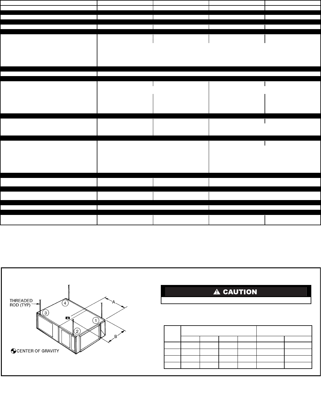
NOTE:
Fasten threaded rods through holes in end frames. Use 2 rods on each
side of unit for a total of 4.
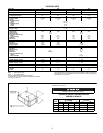
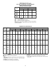
OPERATING WEIGHT DISTRIBUTION AND
CENTER OF GRAVITY
All panels must be in place when rigging.
UNIT
502A
WEIGHT (lb/kg)
OF CORNER
DIMENSIONS
(ft-in./mm)
1234 A B
024
93/42 108/49 139/63 120/54 2-5 /737 2-1
5
/
8
/651
036
95/43 113/51 148/67 124/56 2-4
3
/
4
/730 2-2 /660
048
112/51 143/65 183/83 142/64 2-5 /737 2-3 /686
060
114/52 143/65 186/84 147/67 2-4
3
/
4
/730 2-2
3
/
4
/679