


14
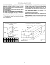
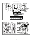
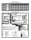
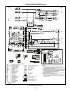
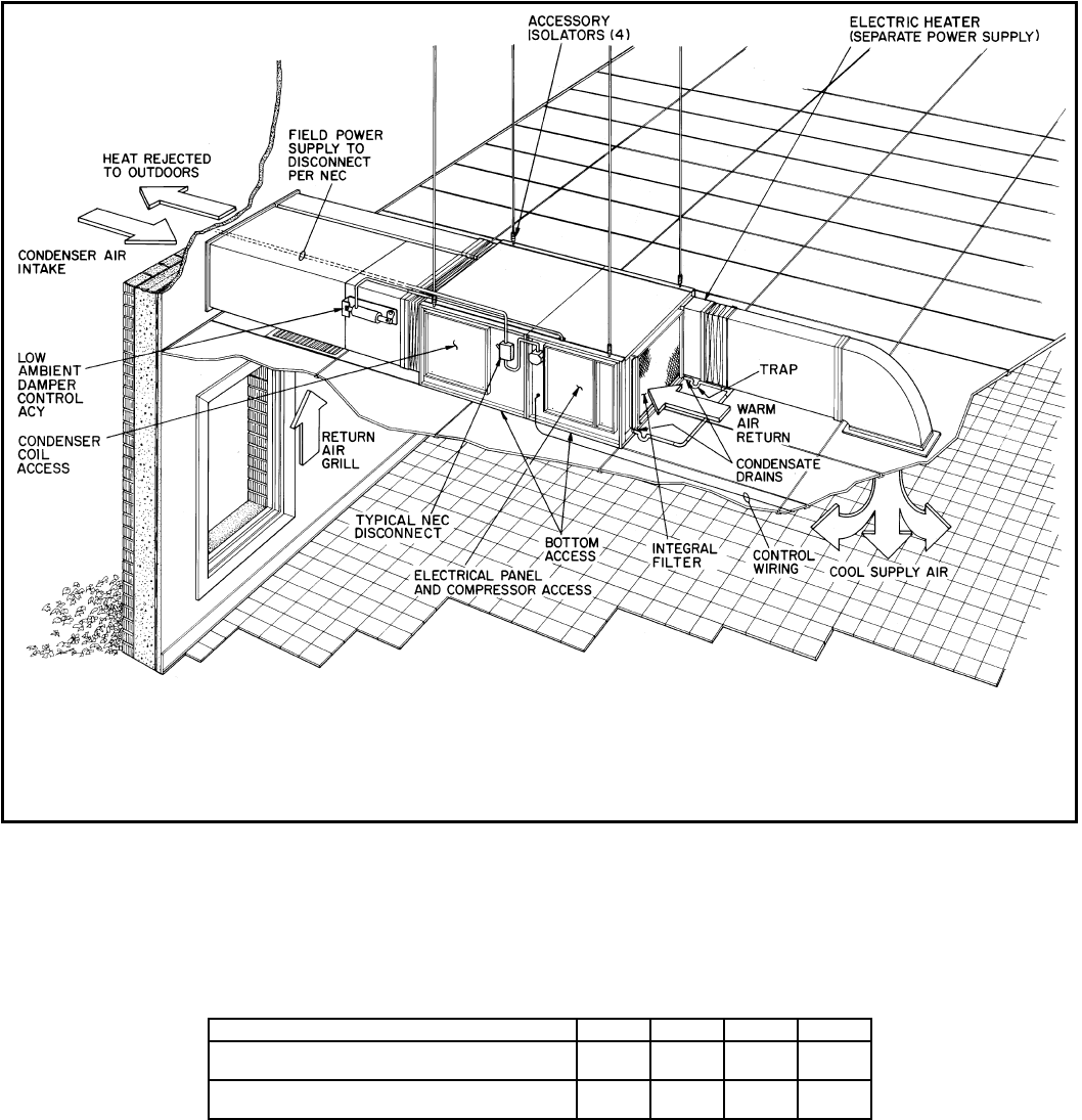
TYPICAL PIPING AND WIRING
APPLICATION DATA
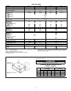
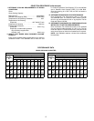
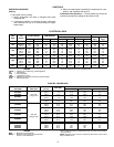
OUTDOOR-AIR TEMPERATURE OPERATING LIMITS (F)
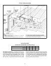
Field Splitting Instructions —
If components are split, maxi-
mum length of refrigerant tubing to be used is 50 ft, assuming
components are installed in same horizontal plane. Condenser
may be mounted up to 12-ft above evaporator. Liquid line tubing
is
3
/
8
-in. OD copper tubing, and discharge line is
1
/
2
-in. OD
copper tubing. Units should always be within line of sight
from each other, or separate NEC (National Electrical Code)
disconnects will be required. Junction boxes should be installed
in both the evaporator and condenser sections adjacent to
D-shaped grommets, to provide a location to splice the outdoor-
fan motor factory wiring (no. 16 AWG [American Wire Gage],
4
/
64
-in. thick insulation). Field wiring should be a minimum of
no. 16 AWG,
4
/
64
-in. thick insulation. Check all applicable electri-
cal codes to ensure proper compliance.
UNIT 502A 024 036 048 060
Without Head Pressure Control Minimum
35 35 40 40
Maximum
126 126 126 126
With Head Pressure Control Minimum
0000
Maximum
126 126 126 126
LEGEND
NEC —
National Electrical Code
NOTES:
1. Wiring and piping shown are not intended for or to include all
details for specific installation.
2. All wiring must comply with applicable local and national codes.
3. All piping must follow standard refrigerant piping techniques.
4. For other installation details refer to Installation Instructions.
5. If unit sections are field split, 8 threaded support rods are required.
6. Ensure condenser air recirculation is minimized.