


11
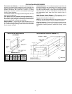
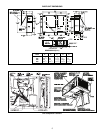
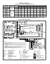
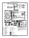
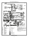
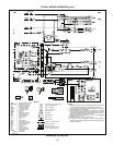
TYPICAL WIRING SCHEMATICS (cont)
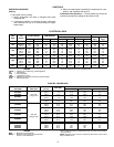
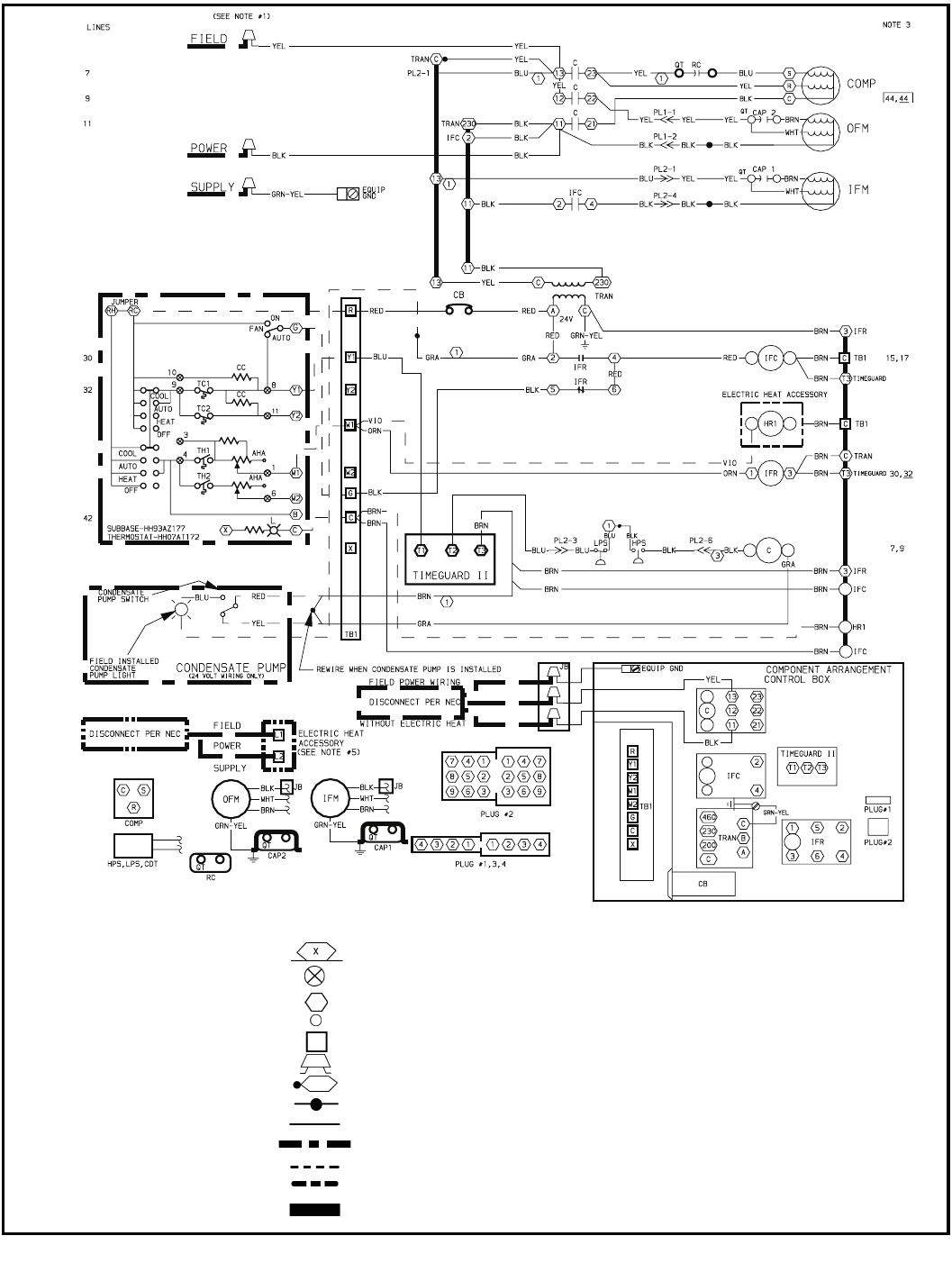
LEGEND
AHA —
Adjustable Heat Anticipator
C —
Contactor Compressor
CAP —
Capacitor
CB —
Circuit Breaker
CC —
Cooling Compensator
CDT —
Compressor Discharge Thermostat
COMP —
Compressor Motor
EQUIP —
Equipment
FU —
Fuse
GND —
Ground
HPS —
High-Pressure Switch
HR —
Heater Relay
IFC —
Indoor-Fan Contactor
IFM —
Indoor-Fan Motor
IFR —
Indoor-Fan Relay
JB —
Junction Box
L —
Light
LPS —
Low-Pressure Switch
NS —
Night Setback Switch
OAT —
Outdoor-Air Thermostat
OFC —
Outdoor-Fan Contactor
OFM —
Outdoor-Fan Motor
PL —
Plug Assembly
QT —
Quadruple Terminal
RC —
Run Capacitor
SW —
Switch
TB —
Terminal Block
TC —
Thermostat-Cooling
TH —
Thermostat-Heating
TRAN —
Transformer
Marked Wire
Denotes connection point between
subbase and thermostat
Terminal (Marked)
Terminal (Unmarked)
Terminal Block
Field Splice
Splice (Marked)
Factory Splice
Factory Wiring
Accessory or Optional Wiring
Field Control Wiring
Field Power Wiring
To indicate common potential
only, not to represent wiring
502A024, 230-1-60 Units
NOTES:
1. Neutral for 240/416 v supply (Canada only).
2. If any original wires furnished must be replaced, it should be
replaced with 90 C or its equivalent.
3. Numbers indicate the line location of used contacts. A bracket
over 2 numbers signifies a single-pole double-throw contact. An
underlined number signifies a normally closed contact. Plain (no
line) number signifies a normally open contact.
4. Must use thermostat HH07AT170, 172 or 174 with subbase
HN63AZ176, 177 or 179.
5. Separate field power supply required for electric heater
accessory.