


4. If furnace is operating properly and LED indicates proper
operation, replace control access door.
5. Component Test can also be initiated by performing the
following:
a. Remove control access door.
b. Remove blower access door.
c. Manually close blower access door switch.
WARNING: Blower access door switch opens 115-v
power to control. No component operation can occur.
Caution must be taken when manually closing this switch
for service purposes. Failure to follow this warning could
result in personal injury or death.
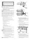
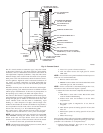
d. BRIEFLY short (jumper) TEST, 3/16 in. quick connect
terminal on control (adjacent to LED status light), and
C
OM-24V terminal on furnace control thermostat termi-
nal block. (See Fig. 6.)
NOTE: If TEST to C
OM-24V terminals are jumpered longer than
2 sec, LED will flash rapidly, and test request will be ignored.
e. Component Test will function as described in item 2
above.
f. Check LED status.
g. If LED status indicates proper operation, RELEASE
BLOWER ACCESS DOOR SWITCH, replace blower
access door, and replace control access door.
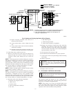
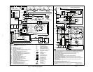
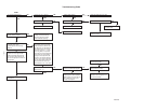
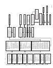
WIRING DIAGRAMS
Refer to Fig. 5, 6, and 7 for wiring diagrams.
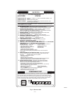
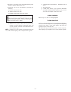
TROUBLESHOOTING
Refer to service label. (See Fig. 8.) The Troubleshooting Guide can
be a useful tool in isolating furnace operation problems. Beginning
with the word “Start,” answer each question and follow the
appropriate arrow to the next item.
The Guide will help you identify the problem or failed component.
After replacing any component, verify correct operation sequence.
—9—