


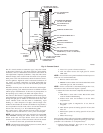
(5.) Repeat foregoing procedures until each cell in
furnace has been cleaned.
(6.) Using vacuum cleaner, remove residue from each
cell.
(7.) Using vacuum cleaner with soft brush attachment,
clean burner assembly.
(8.) Reinstall cell inlet plates and burner assembly. Care
must be exercised to center burners in cell openings.
10. Clean flame sensor with fine steel wool
11. Remove old sealant from center panel and collector box
flange and apply new sealant to collector box flange and
reinstall on center panel, making sure all 8 screws are
secure.
NOTE: A releasing agent such as PAM cooking spray or equiva-
lent (must not contain corn or canola oil, aromatic or halogenated
hydrocarbons or inadequate seal may occur) and RTV sealant
(G.E. 162, 6702, or Dow-Corning 738) are needed before starting
installation. DO NOT substitute any other type of RTV sealant.
G.E. 162 (P771-9003) is available through RCD in 3-oz tubes.
12. Reinstall relief box and inducer assembly.
NOTE: If inducer assembly gasket is damaged, use RTV sealant
to seal inducer assembly to collector box.
NOTE: A releasing agent such as PAM cooking spray or equiva-
lent (must not contain corn or canola oil, aromatic or halogenated
hydrocarbons or inadequate seal may occur) and RTV sealant
(G.E. 162, 6702, or Dow-Corning 738) are needed before starting
installation. DO NOT substitute any other type of RTV sealant.
G.E. 162 (P771-9003) is available through RCD in 3-oz tubes.
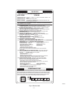
13. Reconnect wires to the following components:
a. Blocked vent safeguard switch.
b. Inducer motor.
c. Pressure switch.
d. Limit overtemperature switch(es).
e. Gas valve.
f. Hot surface ignitor.
g. Flame-sensing electrode
h. Flame rollout switch(es), if applicable.
14. Reinstall vent connector to furnace flue collar. After fully
assembling vent connector to furnace flue collar, securely
fasten vent connector to flue collar with 2 field-supplied,
corrosion-resistant, sheet metal screws located 180 degrees
apart and midway up the collar.
15. Turn electrical power and gas to ON.
16. Set thermostat and check furnace for proper operation.
17. Verify blower airflow and speed changes between heating
and cooling.
18. Check for gas leaks.
WARNING: Never use a match or other open flame to
check for gas leaks. Use a soap-and-water solution. A
failure to follow this warning could result in fire, personal
injury, or death.
19. Replace control access door.
IV. ELECTRICAL CONTROLS AND WIRING
CAUTION: There may be more than 1 electrical supply
to the unit. Check accessories and cooling the unit for
additional electrical supplies.
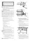
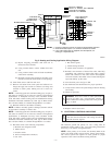
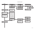
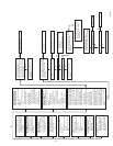
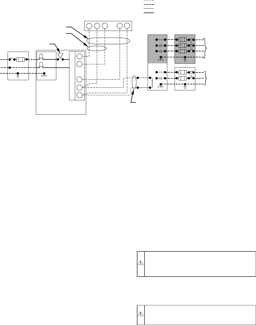
The electrical ground and polarity for 115-v wiring must be
maintained properly. Refer to Fig. 5 for field wiring information
and to Fig. 7 for furnace wiring information.
NOTE: If the polarity is not correct, the STATUS LED on the
control will flash rapidly and prevent the furnace from heating.
The control system also requires an earth ground for proper
operation of the control and flame-sensing electrode.
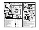
Fig. 5–Heating and Cooling Application Wiring Diagram
A98521
115-V FIELD-
SUPPLIED
DISCONNECT
AUXILIARY
J-BOX
24-V
TERMINAL
BLOCK
THREE-WIRE
HEATING-ONLY
FIVE WIRE
NOTE 1
NOTE 2
FIELD-SUPPLIED
DISCONNECT
CONDENSING
UNIT
TWO
WIRE
FURNACE
C
O
N
T
R
O
L
R
G
C
WCR GY
GND
GND
FIELD 24-V WIRING
FIELD 115-, 208/230-, 460-V WIRING
FACTORY 24-V WIRING
FACTORY 115-V WIRING
208/230- OR
460-V
THREE
PHASE
208/230-V
SINGLE
PHASE
BLOWER DOOR SWITCH
WHT
BLK
WHT
BLK
NOTES: Connect Y-terminal in furnace as shown for proper blower operation.
Some thermostats require a "C" terminal connection as shown.
If any of the original wire, as supplied, must be replaced, use
same type or equivalent wire.
W
Y
GND
THERMOSTAT
TERMINALS
1.
2.
3.
—5—