


b. Remove filter cabinet door.
c. Slide filter out of cabinet.
d. If equipped with permanent, washable filter, clean filter
by spraying cold tap water through filter in opposite
direction of airflow. Rinse filter and let dry. Oiling or
coating of the filter is not recommended.
e. If equipped with factory-specified disposable media
filter, replace only with media filter having the same part
number and size.
f. Slide filter into cabinet.
g. Replace filter cabinet door.
h. Turn on electrical supply to furnace.
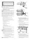
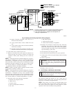
2. Filters installed in side(s) and/or bottom of blower compart-
ment (See Fig. 2)
a. Disconnect electrical power before removing access
doors.
b. Remove blower and control access doors.
c. Release filter retainer from clip at front of furnace
casing. (See Fig. 2.) For side return, clips may be used on
either or both sides of the furnace.
d. Slide filter(s) out.
e. Furnaces are equipped with permanent, washable filters.
Clean filters with tap water. Spray water through filter in
opposite direction of airflow.
f. Rinse and let dry. Oiling or coating of filter is NOT
recommended or required.
g. Reinstall filter(s)
h. Replace blower and control access doors
i. Restore electrical power to furnace.
II. BLOWER MOTOR AND WHEEL
The following items should be performed by a qualified service
technician:
To ensure long life, economy, and high efficiency, clean accumu-
lated dirt and grease from blower wheel and motor annually.
The inducer and blower motors are pre-lubricated and require no
additional lubrication. These motors can be identified by the
absence of oil ports on each end of the motor.
Clean blower motor and wheel as follows:
1. Turn off electrical supply to furnace.
2. Remove control and blower access door.
3. Disconnect blower leads from furnace control. Notice wire
color and location for reassembly.
All other factory wires can be left connected, but field
thermostat connections may need to be disconnected de-
pending on their length and routing.
4. Remove 2 screws securing control and transformer support
to furnace.
5. Hang control and transformer support to side of furnace
casing.
6. Remove screws holding blower assembly to blower deck
and slide blower assembly out of furnace.
7. Clean blower wheel and motor using a vacuum with soft
brush attachment. Do not remove or disturb balance weights
(clips) on blower wheel blades. The blower wheel should
not be dropped or bent as balance will be affected.
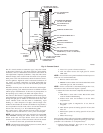
8. If a greasy residue is present on blower wheel, remove
wheel from the blower housing and wash it with an
appropriate degreaser. To remove wheel:
a. Mark blower wheel location on shaft before disassembly
to ensure proper reassembly.
b. Loosen setscrew holding blower wheel on motor shaft.
NOTE: Mark blower mounting arms, motor, and blower housing
so motor and each arm is positioned at the same location during
reassembly.
c. Mark blower wheel orientation and cutoff plate location
to ensure proper reassembly.
d. Remove screws securing cutoff plate and remove cutoff
plate from housing.
e. Remove bolts holding motor and motor mounts to
blower housing and slide motor and mounts out of
housing. Disconnect capacitor and ground wire attached
to blower housing before removing motor. Motor mount
belly band need not be removed unless motor is to be
replaced.
f. Remove blower wheel from housing.
CAUTION: The blower wheel should not be dropped or
bend as balance will be affected.
9. Reassemble motor and blower by reversing items 9a
through 9f. Be sure to reattach ground wire.
10. Reinstall blower assembly in furnace.
11. Reinstall control and transformer support assembly in
furnace.
12. Reconnect blower leads to furnace control.
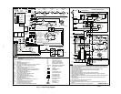
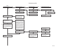
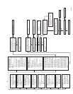
Refer to furnace wiring diagram (See Fig. 7), and connect
thermostat leads if previously disconnected.
NOTE: Refer to Table 1 for motor speed lead relocation if leads
were not identified before disconnection
CAUTION: Heating air speed selection MUST be ad-
justed to provide proper temperature rise as specified on
the rating plate. Failure to adjust the heating speed may
shorten heat exchanger life.
13. Turn on electrical supply. Manually close blower access
door switch. Use a piece of tape to hold switch closed.
Check for proper rotation and speed changes between
heating and cooling by jumpering R to W and then R to Y
on furnace control thermostat terminals.
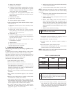
TABLE 1—SPEED SELECTOR
COLOR SPEED
FACTORY-
ATTACHED
TO
Black High Cool
Yellow (When
Present)
Medium High Spare
Blue Medium Low Heat
Red Low Spare
White Common L2/COM
—3—