


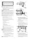
The 24-v circuit contains an automotive-type, 3-amp fuse located
on the control. (See Fig. 6.) Any shorts of the 24-v wiring during
installation, service, or maintenance will cause this fuse to blow. If
fuse replacement is required, use ONLY a 3-amp fuse. The control
LED will display status code 24 when fuse needs to be replaced.
With power to the unit disconnected, check all electrical connec-
tions for tightness. Tighten all screws on electrical connections. If
any smoky or burned connections are found, disassemble the
connection, clean all parts, strip wire, and reassemble properly and
securely.
Reconnect electrical power to the unit and observe unit through 1
complete operating cycle. Electrical controls are difficult to check
without proper instrumentation; if there are any discrepancies in
the operating cycle, contact your dealer and request service.
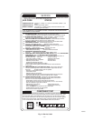
The control in this furnace is equipped with an LED status light to
aid in installation, servicing, and troubleshooting. It can be viewed
through the sight glass or window on the blower access door. The
control indicates status with the LED on continuously, rapid
flashing, or a code composed of 2 digits. (The first digit is the
number of short flashes, the second is the number of longs flashes.)
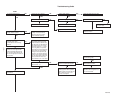
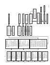
For an explanation of status codes, refer to service label located on
blower access door, Fig. 8, or the troubleshooting guide.
The control stores 1 status code (the last status code to occur) for
a period of 48 hr or until the 115- or 24-v power is interrupted.
NOTE: Look into blower access door sight glass for current LED
status BEFORE removing the blower access door. Removing
blower access door will open blower access door switch and
terminate 115-v power to control, and status code will be erased.
1. To retrieve status code, proceed with the following:
NOTE: NO thermostat signal shall be present at control, and all
blower off delays must be completed.
a. Leave 115-v power to furnace turned on.
b. Look into blower access door sight glass for current
LED status.
NOTE: Leave blower access panel installed to maintain power to
control to view current LED status.
c. Remove control access door.
d. BRIEFLY remove either wire from the main limit switch
until LED goes out, then reconnect it.
NOTE: If wire to main limit is disconnected longer than 4 sec,
main blower starts, and retrieval request is ignored.
2. When above items have been completed, the following will
occur:
a. LED flashes a status code 4 times. Record this status
code for further troubleshooting.
b. Inducer motor starts and continues to run the entire
component test.
c. Hot surface ignitor is energized for 15 sec, then de-
energized.
d. Main blower operates at heating speed for 10 sec, then
turns off.
e. Main blower operates at cooling speed for 10 sec, then
turns off.
f. Inducer motor stops.
Items a through e above will assist in furnace troubleshooting since
all components are functionally operated except the gas valve. This
procedure is also referred to as “Component Test.”
3. Operate furnace through 1 heat cycle to test for proper
operation and check LED status.
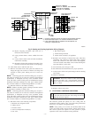
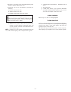
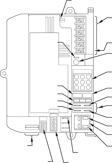
Fig. 6—Furnace Control
A99258
G
R
Y
W
3-AMP FUSE
C
OM
24V
HUMIDIFIER TERMINAL
(24-VAC 0.5 AMP MAX)
LED OPERATION &
STATUS LIGHT
HARNESS CONNECTOR
24V TRANSFORMER SEC-2
SPARE 1
SPARE 2
EAC 1 (BLACK)
EAC-ELECTRONIC AIR CLEANER
TERMINALS (115-VAC 1.0 AMP MAX)
EAC 2 (WHITE)
115-VAC (L2) NEUTRAL
CONNECTION
24V THERMOSTAT
TERMINALS
BLOWER SPEED
SELECTION TERMINALS
INDUCER MOTOR
CONNECTOR
115-VAC (L1)
POWER
SUPPLY
HOT SURFACE
IGNITER
CONNECTOR
HEAT
COOL
BLOWER OFF DELAY
ADJUSTMENT SWITCH
SEC-1
TEST/TWIN
HUM
—6—