


17. Use a stiff brush and vacuum cleaner to clean inside of
primary drum.
CAUTION: Never use incendiary type cleaners (smoke
sticks) for cleaning!
WARNING: For all heat exchanger plates that have
been removed, the gaskets MUST be replaced. Failure to
replace gaskets could lead to heat exchanger leakage,
sooting, and a hazardous condition which could lead to
bodily harm.
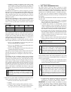
18. Before reassembly, heat exchanger and combustion cham-
ber should be inspected to determine if replacement is
required. After cleaning, place combustion chamber back
into primary drum and secure with "B" screws. Ensure that
cover plate gasket is in place before tightening screws. Care
must be taken not to damage combustion chamber. The "B"
screws should be tightened to 35-45 lb-in.
19. Tighten "A" nuts to 30 lb-in. of torque (firm, but not overly
tight).
20. Replace intermediate panel, observation tube collar, obser-
vation door, limit wiring, and oil burner.
21. Replace collector box on secondary tube flange, ensuring
proper placement of gasket. Tighten screws to 35-45 lb-in.
of torque.
22. Replace top partition, inside collar on flue pipe, top rear
panel, outside flue collar, and blower door.
23. Reconnect flue pipe and oil line(s).
24. Readjust burner for proper operation. Check limit operation
as outlined in Limit Control Check section.
IV. BLOWER OILING AND REMOVAL
Periodic oiling of blower motor may be necessary. Check for
instructions on inside of blower access door.
If it is ever necessary to remove blower from furnace:
1. Turn off all electrical power to furnace.
2. Remove blower door.
3. Remove screws securing blower legs to blower rails
mounted on bottom panel of furnace.
4. Slide blower forward on rails toward rear of unit until motor
wire connections at terminal block on motor can easily be
reached and disconnected.
5. Disconnect motor wires at terminal block on motor.
6. Remove blower from unit.
7. Reverse items 1 through 6 to reinstall blower. Refer to
wiring diagram (Fig. 7) of these instructions or diagram
located on inside of louvered door to properly rewire unit.
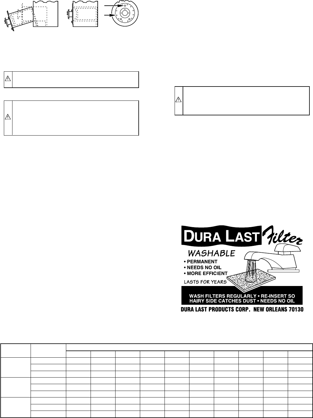
V. KEEPING FILTERS CLEAN
WARNING: Never operate unit without a filter or with
filter access door removed. Failure to adhere to this
warning could lead to a hazardous condition which could
lead to equipment damage and bodily harm.
As a homeowner, keeping filters clean is your most important
responsibility. A dirty filter reduces efficiency of your system,
causes erratic performance of controls, and could result in damage
to motor or heating element.
1. Inspect filters at regular intervals depending upon dirt
conditions. For new homes, check filters every week for 4
consecutive weeks. In all cases, inspect filters at least every
3 to 4 weeks when system is in constant operation. Replace
or clean filter at least at beginning of each season (heating
and cooling) and thereafter as needed.
2. If a permanent filter is used, it can be cleaned with cold
water and soap.
Be sure that filter is thoroughly dry before installing back into
furnace.
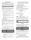
→ TABLE 5—AIRFLOW DATA (CFM)
UNIT
SIZE
BLOWER
SPEED
EXTERNAL STATIC PRESSURE IN. WC
0.1 0.2 0.3 0.4 0.5 0.6 0.7 0.8 0.9 1.0
036105
High 1795 1735 1675 1605 1550 1485 1425 1350 1275 1220
Medium 1365 1335 1305 1275 1255 1215 1155 1105 1050 985
Low 995 965 945 925 900 870 825 775 725 670
048125
High 1905 1845 1770 1695 1630 1565 1490 1425 1325 1220
Medium 1750 1675 1620 1560 1500 1440 1370 1305 1235 1130
Low 1390 1350 1305 1260 1220 1180 1120 1060 985 880
060155
High 2025 1960 1905 1850 1800 1665 1575 1500 1415 1315
Medium 1885 1825 1760 1705 1640 1565 1500 1430 1350 1265
Low 1555 1490 1445 1410 1350 1280 1230 1155 1085 1005
NOTES: 1. Airflow values in cubic ft per minute (CFM) rounded to nearest 5 CFM.
2. Data taken without filters in place.
Fig. 4—Removing Combustion Chamber
A96398
A
B
A95103
—8—