


ELECTRICAL
The appliance must be installed in accordance with current
ANSI/NFPA 70 National Electrical Code, CSA C22.1 Canadian
Electrical Code Part 1, and/or local codes.
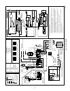
The control system depends on correct polarity of power supply.
Connect HOT wire (H) and NEUTRAL wire (N) as shown in Fig.
7.
A separate line voltage supply MUST be used with a fused
disconnect switch or HACR-type circuit breaker between main
power panel and unit. (See Fig. 7.) Disconnecting means must be
within sight from furnace.
WARNING: The unit cabinet must have an uninter-
rupted or unbroken electrical ground to minimize per-
sonal injury if an electrical fault should occur. A green
ground screw is provided in control box for this connec-
tion.
Use only copper wire for 115-v supply service to unit.
Metallic conduit (where required/used) may terminate at side panel
of unit. It is not necessary to extend conduit inside unit from side
panel to control box.
When replacing any original furnace wiring, use only 105°C No.
16 AWG copper wire.
Instructions for wiring thermostat (field supplied) are packed in
thermostat box. Make thermostat connections as shown in Fig. 7 at
24-v terminal board on control box.
When installing optional accessories to this appliance, follow
manufacturer’s Installation Instructions included with accessory.
Other than wiring for thermostat, wire with a minimum of type "T"
insulation (63°F rise) must be used for accessories.
Two 1/4-in. quick-connect terminals marked EAC and N5 are
provided for electronic air cleaner (EAC) connection. (See Fig. 7.)
These terminals are energized with 115v (0.5-amp maximum)
during blower motor operation.
Two 1/4-in. quick-connect terminals marked HUM and N6 are
provided for 115-v humidifier connection. (See Fig. 7.) These
terminals are energized with 115v (0.5-amp maximum) during any
call for heat.
FILTERS
WARNING: Never operate unit without a filter or with
filter access door removed. Failure to adhere to this
warning could lead to a hazardous condition which could
lead to equipment damage and bodily harm.
An internal filter is provided as standard equipment with furnace.
Refer to Keeping Filters Clean section for filter cleaning informa-
tion.
OPERATIONAL CHECKOUT
DO NOT START BURNER UNLESS BLOWER ACCESS
DOOR IS SECURED IN PLACE.
Installation of furnace is now complete and operational checkout
may be performed.
I. START-UP
1. Check wiring against wiring diagram shown in Fig. 7.
2. Open valve on oil supply line.
3. Reset primary control.
4. Set thermostat above room temperature.
5. Set main electrical switch to ON position. Burner should
start.
DO NOT TAMPER WITH UNIT OR CONTROLS—CALL
YOUR SERVICE TECHNICIAN.
II. RECOMMENDED INSTALLATION PRACTICES AND
COMBUSTION CHECK
In order to obtain optimum performance from oil burner, the
following setup procedures must be followed:
1. A test kit (Bacharach No. 5022 kit or equivalent) to measure
smoke, stack draft, over-fire draft, CO
2
, and stack tempera-
tures MUST be used in order to obtain proper air band
setting. Although all of the above measurements are re-
quired for optimum setup and efficiency data, the most
important readings that must be taken are smoke number,
over-fire draft, and stack draft.
2. The proper smoke number has been established by engi-
neering tests to be between 0 and 1. This degree of smoke
emission is commonly referred to as a "Trace" of smoke. It
is recommended to use a Bacharach true spot smoke test set
or equivalent.
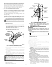
3. In order to ensure proper draft through furnace, a baromet-
ric draft regulator (supplied with furnace) must be installed
as close to outlet of furnace as possible.
In order for this device to function properly, barometric
damper must be mounted with hinge pins horizontal and
face of damper vertical. (See instructions included with
damper.) The draft regulator should be adjusted after
furnace has been firing for at least 10 minutes, and stack
draft should be measured and set between -0.025 and -0.035
in. wc. The draft should be checked with a Bacharach MZF
draft gage or equivalent.
4. The over-fire draft, which is taken through hole provided in
observation door, is a measurement necessary to determine
if there is a blockage between oil burner and flue outlet.
There should be a pressure drop of between 0.005 and 0.015
in. wc through furnace. This would set the range of the
over-fire draft between -0.01 and -0.03 in. wc. A reading
above -0.01 in. wc (for example +0.1 in. wc) would indicate
that furnace is in an extremely high-pressure condition in
primary section. This condition may be caused by excessive
combustion air due to air band being too wide open or a lack
of flue draft (chimney effect) or some other blockage, such
as soot, in secondary section of heat exchanger.
5. The CO
2
and stack temperature instruments enable you to
obtain data required to determine thermal efficiency of
furnace.
6. An oil filter should be installed as close to burner as
possible with ALL oil burners and is essential on lower
firing rate burners. We recommend the use of a low
pressure drop oil filter such as the General Filter, Inc. model
#1A-25A or equivalent. It is critical that oil capacity be
equivalent or greater than fuel pump gear capacity. For a
2-pipe system, this is 25 gph.
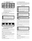
7. The oil pressure regulator is factory set to give nozzle oil
pressures of 100 psig. The firing rate noted on nameplate
may be obtained with "standard" nozzles by adjusting pump
pressure as noted in Table 4 or on label on furnace.
On a new installation, air entrapped in oil line leading from
tank to nozzle must be thoroughly purged in order to
prevent excessive after drip. The oil pump is provided with
a special fitting which allows purging of any air between
tank and oil pump. The proper procedure for performing
this operation is as follows:
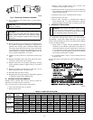
a. Place a piece of clear plastic 1/4-in. diameter tubing over
purge fitting on oil pump.
b. Start oil burner, then open purge fitting and allow burner
to run until purge tube is completely free of air bubbles.
—5—
→
→
→
→