


c. Tighten purge fitting. Allow oil to run to nozzle and fire
burner.
d. If purging takes longer than 30 sec and no flame has
been established, burner stops. Push reset button on top
of primary control to restart burner.
e. For detailed information on operation of primary control,
refer to instructions included with furnace.
III. FAN ADJUSTMENT CHECK
This furnace is equipped with a 3-speed direct-drive motor to
deliver a temperature rise (between return and supply plenums)
within range specified on rating plate at external duct static
pressure noted on rating plate.
CAUTION: When operating furnace in heating mode,
static pressure and temperature rise (supply-air tempera-
ture minus return-air temperature) must be within those
limits specified on rating label. Failure to follow this
warning could lead to severe furnace damage.
Adjust fan speed so that temperature rise is within rise range
specified on rating plate. Consult wiring diagram for speed
changes on direct-drive motor.
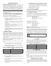
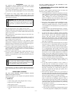
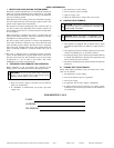
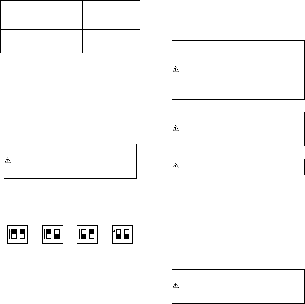
To adjust fan off time, set DIP switches on control board to obtain
desired timing. (See Fig. 1.)
IV. LIMIT CONTROL CHECK
After furnace has been in operation for at least 15 minutes, restrict
return-air supply by blocking filters or closing return registers and
allow furnace to shut down on high limit. The burner should shut
off, and main blower should continue to run.
Remove restriction, and burner should come back on in a few
minutes.
V. FOR YEAR-ROUND AIR CONDITIONING
This furnace is designed for use in conjunction with cooling
equipment to provide year-round air conditioning. The blower has
been sized for both heating and cooling, however, fan motor speed
may need to be changed to obtain necessary cooling airflow.
VI. HEATING
The blower speed is factory set to deliver required airflow at
normal duct static pressure.
VII. COOLING
The blower speed may be field adjusted to deliver required airflow
for cooling application. (See Table 5.)
VIII. CONSTANT BLOWER SWITCH
This furnace is equipped with a constant low-speed blower option.
Whenever room thermostat is not calling for heating or cooling,
blower runs on low speed in order to provide air circulation. If
constant blower option is not desired, the rocker switch on side of
control box may be used to turn off constant speed.
MAINTENANCE
WARNING: The ability to properly perform mainte-
nance on this equipment requires certain expertise, me-
chanical skills, tools, and equipment. If you do not
possess these, do not attempt to perform any maintenance
on this equipment other than those procedures recom-
mended in the User’s Manual. FAILURE TO FOLLOW
THIS WARNING COULD RESULT IN POSSIBLE
DAMAGE TO THIS EQUIPMENT, SERIOUS PER-
SONAL INJURY, OR DEATH.
WARNING: Before performing any service functions,
unless operations specifically require power to be on,
make sure all utilities are turned off upstream of appli-
ance. Failure to comply with this warning will cause a fire
hazard and/or bodily harm.
WARNING: To avoid personal injury, make sure elec-
trical supply power is off before servicing.
I. GENERAL
In order to keep this furnace in good operating condition and to
maintain its warranty, the furnace MUST be serviced on an annual
basis. This servicing includes a nozzle change, a burner inspection,
a visual check of tube passages through flue outlet and cleanout
ports, and a visual inspection of combustion chamber when burner
is removed.
Depending on above inspection, service could also include a
cleaning and vacuuming of heat exchanger tubes and possibly the
heat exchanger drum section.
Removal of any heat exchanger components which are sealed by
gaskets requires replacement of gasket.
WARNING: Failure to replace any heat exchanger gas-
kets with new gaskets when any heat exchanger plates or
covers are removed could lead to heat exchanger leakage,
sooting, and/or a hazardous condition capable of causing
bodily harm.
This furnace should never be operated without an air filter.
Disposable filters should be replaced at least once a year. If
equipped to provide cooling, filters should be replaced a minimum
of twice a year. Permanent filters should be cleaned at least twice
a year.
ALWAYS KEEP MAIN OIL VALVE TURNED OFF IF
BURNER IS SHUT DOWN FOR AN EXTENDED PERIOD OF
TIME.
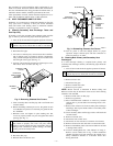
II. OIL BURNER
Contact your service technician for service.
Lubricate burner motor with SAE 10 oil. Once each year, pour 2
teaspoons of oil slowly into each oil cup.
To maintain proper performance, oil burner nozzle must be
replaced once a year.
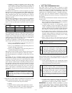
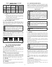
→ TABLE 4—BURNER, NOZZLE, AND PUMP
PRESSURE CHART
UNIT
SIZE
FIRING
RATE
GAL/HR (US)
PUMP
PRESSURE
(PSIG)
BECKETT OIL BURNER
Model Nozzle
036105 0.76 103 AFG
0.75 gph
70° Hollow
048125 0.90 100 AFG
0.90 gph
70° Hollow
060155 1.12 104 AFG
1.10 gph
70° Hollow
Fig. 1—Fan Off Time DIP Switch Settings
(Black Box Represents Switch Position)
A95115
12
60 Sec
12
90 Sec
DELAY OFF DIP SWITCH SETTINGS
12 1212
120 Sec
12
150 Sec
—6—
→
→