


VENTING INSTRUCTIONS
Venting of furnace should be to the outside and in accordance with
local codes or requirements of local utility.
OIL-FIRED APPLIANCES SHALL BE CONNECTED TO
FLUES HAVING SUFFICIENT DRAFT AT ALL TIMES TO
ENSURE SAFE AND PROPER OPERATION OF APPLIANCE.
For additional venting information, refer to ANSI/NFPA 211
Chimney, Fireplaces, Vents, and Solid Fuel Burning Appliances
and/or CSA B139 Installation Code.
This furnace is certified for use with Type "L" vent (maximum flue
gas temperature 575°F).
I. PRE-INSTALLATION VENT SYSTEM INSPECTION
Before furnace is installed, it is highly recommended that any
existing vent system be completely inspected.
For any chimney or vent, this should include the following:
1. Inspection for any deterioration in chimney or vent. If
deterioration is discovered, chimney must be repaired or
vent must be replaced.
2. Inspection to ascertain that vent system is clear and free of
obstructions. Any blockage must be cleared before install-
ing furnace.
3. Cleaning chimney or vent if previously used for venting a
solid fuel burning appliance or fireplace.
4. Confirming that all unused chimney or vent connections are
properly sealed.
5. Verification that chimney is properly lined and sized per the
applicable codes. (Refer to list of codes in Safety Consid-
erations section.)
II. MASONRY CHIMNEY
This furnace can be vented into an existing masonry chimney. This
furnace must not be vented into a chimney servicing a solid fuel
burning appliance. Before venting furnace into a chimney, the
chimney MUST be checked for deterioration and repaired if
necessary. The chimney must be properly lined and sized per local
or national codes.
If furnace is vented into a common chimney, the chimney must be
of sufficient area to accommodate the total flue products of all
appliances vented into chimney.
The following requirements are provided for a safe venting
system:
1. Be sure that chimney flue is clear of any dirt or debris.
2. Be sure that chimney is not servicing an open fireplace.
3. Never reduce pipe size below minimum certified furnace
pipe size as shown in Table 2.
4. All pipe should be supported using proper clamps and/or
straps. These supports should be at least every 4 ft.
5. All horizontal runs of pipe should have at least 1/4-in. per
ft of upward slope.
6. All runs of pipe should be as short as possible with as few
turns as possible.
7. Seams should be tightly joined and checked for leaks.
8. The flue pipe must not extend into chimney but be flush
with inside wall.
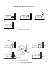
9. The chimney must extend 3 ft above highest point where it
passes through the roof of a building and at least 2 ft higher
than any portion of a building within a horizontal distance
of 10 ft. It shall also be extended at least 5 ft above highest
connected equipment flue collar.
10. Check local codes for any variance.
III. FACTORY-BUILT CHIMNEYS
Listed factory-built chimneys may be used. Refer to chimney
manufacturer’s instructions for proper installation.
IV. HORIZONTAL VENTING
This furnace may be vented horizontally through an outside wall
when installed with 1 of the following auxiliary inducer blowers:
Tjernlund Products, Inc. Model SS1 (SS1C required in Canada)
available from: Tjernlund Products, Inc.
1601 Ninth Street
White Bear Lake, MN 55110-6795
(612) 426-2993
or
Fields Controls Model SWGII-5
(with a CK-60 or CK-61 control kit)
available from: Fields Controls Company
2308 Airport Road
Kinston, NC 28051
(919) 522-3031
NOTE: In both cases, the 24-v wiring schematic included with
inducer is the recommended wiring setup.
The use of either inducer can create a negative pressure in the area
where furnace is located if the proper combustion-air openings are
not available. This negative pressure can lead to excessive heat
being retained in heat exchanger, coking, and fumes. Refer to
NFPA-31 Section 1.5 for proper combustion-air requirements.
CAUTION: USE METALLIC VENT PIPE ONLY!
PLASTIC VENTING MATERIALS ARE PROHIB-
ITED!
OIL BURNER
This furnace is supplied with a high-pressure atomizing retention
head type burner (for use with not heavier than grade 2 Fuel Oil).
The air tube length, from face of mounting plate to extreme face of
end cone, should be as shown in Table 3.
OIL CONNECTIONS
Complete instructions for installation of fuel oil piping will be
found in oil burner Installation Instructions included with furnace.
Oil line entry holes are provided in side panels. Two holes are
provided in each location so that a 2-pipe system may be used if
desired.
A properly sized oil filter should be used with all oil burners and
should be installed as close to burner as possible. For a 2-pipe
system, a minimum capacity of 25 gph is needed.
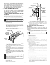
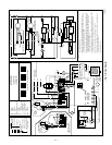
BAROMETRIC DRAFT CONTROL
The barometric draft control shipped with furnace MUST be used
with furnace to ensure proper operation. Instructions for installing
control are packed with control. Refer to Fig. 6 for suggested
locations.
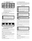
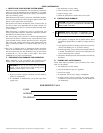
TABLE 2—MINIMUM CERTIFIED FURNACE PIPE SIZE
(IN.)
UNIT SIZE MINIMUM PIPE DIAMETER
036105 5
048125 5
060155 6
→ TABLE 3—OIL BURNER AIR TUBE LENGTH
UNIT SIZE LENGTH (IN.)
036105 5
048125 5
060155 7
—4—
→
→
→
→