


18
8. Turn on gas and electrical supplies to furnace.
9. Verify igniter operation by initiating furnace control self-test
feature or by cycling thermostat.
10. Replace main furnace door.
Procedur e 7 — Electrical Controls and Wiring
ELECTRICAL SHOCK HAZARD
Failure to follow this warning could result in personal injury
or death.
There may be more than 1 electrical supply to the furnace.
Check accessories and cooling unit for additional
electrical supplies.
!
WARNING
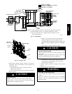
The electrical ground and polarity for 115-v wiring must be
maintained properly . Refer to Fig. 17 for field wiring information
and to Fig. 20 for furnace wiring information.
NOTE: If polarity is not correct, STATUS LED on furnace control
board will flash rapidly and prevent furnace from operating. The
control system also requires an earth ground for proper operation
of furnace control and flame sensor.
The 24-v c ircuit contains an automotive-type, 5-amp fuse located
on the control. (See Fig. 18.) Any direct shorts of the 24-v wiring
during installation, service, or maintenance will cause this fuse to
blow. If fuse replacement is required, use ONLY a 5-amp fuse of
identical size. The control LED will flash status code 24 when fuse
needs to be replaced.
With power to unit disconnected, check all electrical connections
for tightness. Tighten all screws on electrical connections. If any
smoky or burned connections are found, disassemble connection,
clean all parts, strip wire, and reassemble properly and securely.
Reconnect electrical supply to unit and observe unit through 1
complete operating cycle for proper operation.
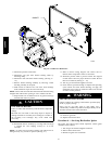
Procedur e 8 — Checking Heat Tape Operation
(If Applicable)
In applications where the ambient temperature around the furnace
is 32°F(0°C) or lower , freeze protection measures are required. If
heat tape has been applied, check to ensure it will operate when
low temperatures are present.
UNIT AND PROPERTY DAMAGE HAZARD
Failure to follow this caution may result in furnace component
damage or property damage.
If this furnace is to be operated in an unconditioned space
where the ambient temperatures may be 32°F(0°C) or lower,
freeze protection measures must be taken. (See Fig. 19.) See
CONDENSATE DRAIN PROTECTION section of
Installation, Start-Up and Operating Instructions.
CAUTION
!
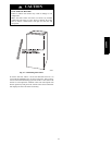
NOTE: Heat tape, when used, should be wrapped around the
condensate drain trap and drain line. There is no need to use heat
tape w ithin the furnace casing. Most heat tapes are temperature
activated, and it is not practical to verify the actual heating of the
tape. Check the following:
1. Check for signs of physical damage to heat tape such as
nicks, cuts, abrasions, gnawing by animals, etc.
2. Check for discolored heat tape insulation. If any damage or
discolored insulation is evident, replace heat tape.
3. Check that heat tape power supply circuit is on.
Procedure 9 — Winterizing
UNIT DAMAGE HAZARD
Failure to follow this caution may result in furnace component
damage.
Freezing condensate left in the furnace will damage
the furnace.
CAUTION
!
If the furnace will be off for an extended period of time in a
structure where the temperature will drop to 32°F(0°C) or below,
winterize as follows:
1. Turn off electrical supply to furnace.
2. Remove main furnace door.
3. Disconnect the 1/2” I.D. rubber hose from the vent drain
fitting (or tee) that is located downstream of the combustion
blower. Insert a funnel into the hose and pour four (4)
ounces of sanitary type (R V) antifreeze into the condensate
trap. Reconnect the 1/2” I.D. rubber hose to the stub the
vent drain fitting. Secure with the hose clamp.
UNIT DAMAGE HAZARD
Failure to follow this caution may result in unit component
damage.
Do not use ethylene glycol (Prestone II antifreeze/coolant or
equivalent automotive type). Failure of plastic components
may occur.
CAUTION
!
4. Disconnect the 5/8” I.D. rubber hose from the condensate
trap. Insert a funnel into the hose and pour four (4) ounces
of sanitary type (RV) antifreeze into the plastic transition
box. Squeeze the hose together near the and quickly
reconnect the 5/8” I.D. rubber hose to the stub on the
condensate trap. Secure with the hose clamp.
5. When you return home, your furnace will be ready to start,
as it is not necessary to drain the antifreeze from the furnace.
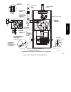
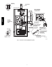
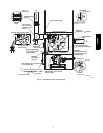
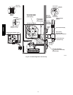
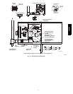
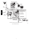
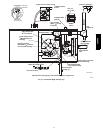
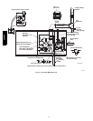
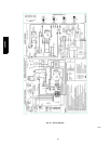
WIRING DIAGRAM
See Fig. 20 for Wiring Diagram.
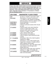
TROUBLESHOOTING
Use the Troubleshooting Guide, the status code LED on the control
and the Component Test to isolate furnace operation problems.
A. Status Codes
For an explanation of status codes, refer to service label located on
front of blower door or Fig. 21.
NOTE: Removing the blower access door will open the blower
access door switch and terminate 115-v power to the control. This
will erase the stored status code.
NOTE: NO thermostat signals should be present at control and all
blower off delays must be completed to view previous codes.
359AAV