


15
Procedure 4 — Cleaning Heat Exchangers
The following items should be performed by a qualified
service technician.
A. Primary Heat Exchangers
If heat exchangers get an accumulation of light dirt or dust on the
inside, they may be cleaned by the following procedure:
NOTE: If heat exchangers get a heavy accumulation of soot and
carbon, both the primary and secondary heat exchangers should be
replaced rather than trying to clean them thoroughly due to their
intricate design. A build-up of soot and carbon indicates that a
problem exists which needs to be c orrected, such as improper
adjustment of manifold pressure, insufficient or poor quality
combustion air, improper vent termination, incorrect size or
damaged manifold orifice(s), improper gas, or a restricted heat
exchanger (primary or secondary). Action must be taken to correct
the problem.
1. Turn off gas and electrical supplies to furnace.
2. Remove main furnace door.
ELECTRICAL SHOCK, UNIT DAMAGE HAZARD
Failure to follow this caution may result in personal injury or
furnace component damage.
Label all wires prior to disconnection when servicing controls.
Wiring errors can cause improper and dangerous operation.
CAUTION
!
3. Disconnect wires or connectors to flame rollout switch, gas
valve, igniter, and flame sensor.
4. Using backup wrench, disconnect gas supply pipe from
gas valve.
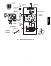
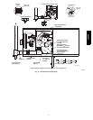
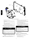
5. Remove screws attaching burner box to cell panel.
(See Fig. 4.)
NOTE: Burner box, manifold, gas valve, and burner assembly
should be removed as 1 assembly.
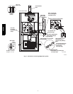
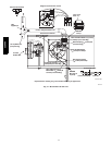
6. Clean heat exchanger openings with a vacuum and a soft
brush. (See Fig. 5.)
NOTE: After cleaning, inspect heat exchangers to ensure they are
free of all foreign objects that may restrict flow of
combustion products.
7. Reverse items 4 and 5 for reassembly.
UNIT MAY NOT OPERATE
Failure to follow this caution may result in improper unit
operation.
The ground wire from the gas valve MUST be attached to the
burner box attachment screw or furnace lockout may occur.
CAUTION
!
8. Refer to furnace wiring diagram and connect wires to flame
rollout switch, gas valve, igniter, and flame sensor.
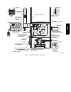
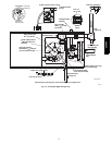
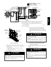
9. Reconnect pressure switch tubes to gas valve and intake
housing. Refer to tube routing label on main furnace door
for proper tube lo cation. Be sure tubes are not kinked.
(See Fig. 6 -- 14.)
10. Turn on gas and electrical supplies to furnace.
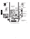
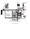
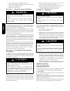
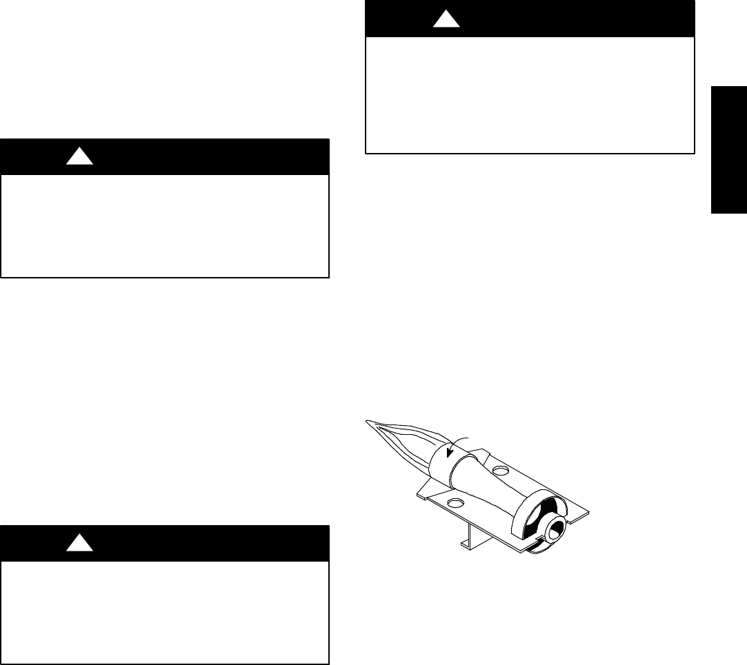
11. Check furnace operation through 2 complete heat operating
cycles. Burner flames should be clear blue, almost
transparent. (See Fig. 15.)
FIRE OR EXPLOSION HAZARD
Failure to follow the safety warnings could result in personal
injury, death, or property damage.
Never test for gas leaks with an open flame. Use a
commercially available soap solution made specifically for the
detection of leaks to check all connections.
!
WARNING
12. Check for gas leaks.
13. Replace main furnace door.
B. Secondary Heat Exchangers
NOTE: The condensing side (inside) of secondary heat
exchangers CANNOT be serv iced or inspected. A small number o f
bottom outlet openings can be inspected by removing inducer
assembly. See Flushing Collector Box and Drainage System
section for details on removing inducer assembly.
Procedure5—FlushingCollectorBoxand
Drainage System
1. Turn off gas and electrical supplies to furnace.
2. Remove main furnace door.
3. Disconnect inducer motor and pressure switch wires
or connectors.
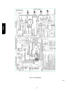
Burner Face
A07734
Fig. 15 -- Burner Flame
359AAV