


3. INSTALLATION
BAS-311F-0, 311F-L, 326F-0
19
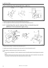
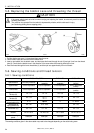
3-20-1. Installing the air unit
Make sure that the air unit does not touch the control box or the work table leg.
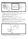
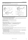
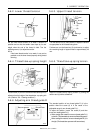
<When installing to the underside of the work table>
1. Remove the two screws (1) and the valve setting plate (2).
2. Turn the valve setting plate (2) upside down, and install it to the underside of the work table using the two wood screws
(3) and washers (4) which are provided as accessories.
3. Install the air unit (5) to the valve setting plate (2) with two screws (1).
4. Connect the air hose (6).
5. Adjust the air pressure. (Refer to “9-10-4. Adjusting the air pressure”.)
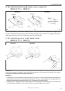
<When installing to a beam>
1. Make holes in the beam as shown in the illustration above. (Button hole diameter is 5.4 mm.)
Pneumatic work clamp ......Pitch 50 mm Reverse work clamp ......Pitch 120 mm
2. Install the air unit (7) to the beam with two accessory screws (8) and two bolts (9).
3. Connect the air hose (10).
4. Adjust the air pressure. (Refer to “9-10-4. Adjusting the air pressure”.)
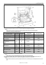
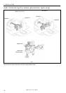
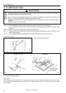
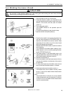
3-20-2. Adjusting the speed controller
The raising and lowering speeds for the work clamp can be adjusted by screwing the knobs on the valve in and out.
Adjust the knob position to set the appropriate speed.
If the upper knob is screwed inward, the work clamp raising speed becomes slower; if it is screwed outward, the
raising speed becomes faster.
If the lower knob is screwed inward, the work clamp lowering speed becomes slower, if it is screwed outward, the
lowering speed becomes faster.
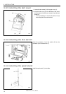
The work clamp can be operated when the power is turned off by pressing the switch.
If the manual button is pushed in and turned to the right, the work clamp can then be held in the raised condition.
Note
The valve knobs should be adjusted so that the left and right sides of the work clamp operate at the same speed.
120 mm
(2)
0320Q 0321Q
50 mm
(1)
(5)
(1)
(6)
(3)
(4)
(2)
(7)
(8)
(10)
(9)