


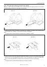
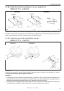

3. INSTALLATION
BAS-311F-0, 311F-L, 326F-0
13
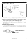
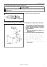
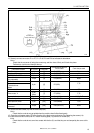
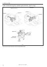
13. Securely connect connectors P1 to P7, P14, P18, P23 and P26 as indicated in table below.
Note
Check that the connector is facing the correct way, and then insert it firmly until it locks into place.
Furthermore, lock the cord clamp at the top.
Machine head connectors
Connection location
No. of pins Cord mark
Connection location on
circuit board
Cord clamps used
X, Y, Sewing sensor 12-pin [1] P1 (ORG) None
Synchronizer 5-pin [2] P2 (SYNCHRO) F
EMERGENCY STOP switch
9-pin [3] P3 (HEAD) None
Solenoid valve
(for pneumatic)
12-pin [4] P4 (VALVE) None
Solenoid
Presser foot
Thread trimmer
Wiper
8-pin [5] P5 (SOL)
F, G
Pulse motor, Y 5-pin [6] P6 (YPM) F,G
Pulse motor, X
5-pin
(blue)
[7] P7 (XPM) F, G
Upper shaft motor 3-pin None P14 (UVM) A, B, C, D, E
Operation panel 10-pin [M] P18 (PANEL) A, B
Head position switch 3-pin [23] P23 (IMSW) A, B
Machine specification select
connector
10-pin [26] P26 (SELECT) None
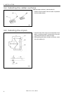
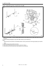
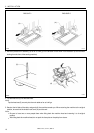
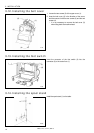
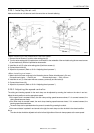
14. Secure the cord bundle (10) with the cord clamp (20).
Note
Check that the cords do not get pulled when the machine head is tilted back gently.
15. Close the cord presser plate (15) in the direction of the black arrow, and secure it by tightening the screws (14).
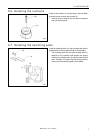
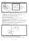
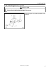
16. Install the control box cover (main P.C. board mounting plate (13)) with the six screws (12).
Note
Check that the cords do not come into contact with the fan (21) and that they are not clamped by the cover at this
time.
1 176S
(10)
Lock the cord
clamp at the top.
(21)
(20)
(12)
(13)