


4
T
he basic installation of this Alarm is similar whether you want to
install one Alarm, or interconnect more than one Alarm. If you are
interconnecting more than one Alarm, you MUST read “Special
R
equirements For Interconnected Alarms” below before you begin
installation.
ELECTRICAL SHOCK HAZARD. Turn off power to the area where
y
ou will install this unit at the circuit breaker or fuse box before
beginning installation. Failure to turn off the power before installa-
tion may result in serious electrical shock, injury or death.
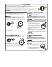
1
. Remove the mounting bracket
from the base, and attach it to
t
he junction box.
2
. Using wire nuts, connect the
power connector to the
household wiring.
3. Plug the power connector into the back of the Alarm.
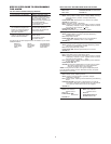
4. Activate the battery back-up by removing the “Pull to Activate
Battery Back-Up” tab. Or, install battery back-up. Battery back-up
cannot work until you install the battery in the correct position
(Match “+” to “+” and “-” to “-”).
5.
Position the base of the Alarm over the mounting bracket, and turn
the Alarm clockwise (right) until the unit is in place. If wall mounted,
adjust unit so words are level.
6. Check all connections.
Improper wiring of the power connector or the wiring leading to
the power connector will cause damage to the Alarm and may
lead to a non-functioning Alarm.
ELECTRICAL SHOCK HAZARD. Do not r
estore power until all
Alar
ms are completely installed. Restoring power before installation
is complete may result in serious electrical shock, injury or death.
7. Make sure the Alarm is receiving AC power. Under normal
operation, the Green power indicator light will shine continuously.
8. If the Green power indicator light does not light,
TURN OFF
POWER TO THE JUNCTION BOX
and recheck all connections.
If all connections ar
e correct and the Green power indicator still
does not light when you restore the power, the unit should be
replaced immediately.
9. Test each Smoke Alarm. Press and hold the Test/Silence button
until the unit alarms.
When testing a series of interconnected
units you must test each unit individually. Make sure all units
alar
m when each one is tested.
If any unit in the series does not alarm, TURN OFF POWER and
r
echeck connections. If it does not alarm when you restore
power, replace it immediately.
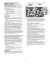
F
OLLOW THESE INSTALLATION STEPS
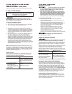
STAND-ALONE ALARM ONLY:
• Connect the white wire on the power connector to the neutral
w
ire in the junction box.
•
Connect the black wire on the power connector to the hot wire
in the junction box.
• Tuck the orange wire inside the junction box. It is used for
i
nterconnect only.
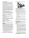
INTERCONNECTED UNITS ONL
Y:
Strip of
f about 1/2” (12 mm) of the plastic coating on the
o
range wire on the power connector.
•
Connect the white wire on the power connector to the neutral
wire in the junction box.
• Connect the black wire on the power connector to the hot wire
i
n the junction box.
•
C
onnect the orange wire on the power connector to the
interconnect wire in the junction box. Repeat for each unit you
a
re interconnecting. Never connect the hot or neutral wires in the
j
unction box to the orange interconnect wire
. Never cross hot
and neutral wires between Alarms.
STAND-ALONE ALARM ONLY:
• If you are only installing one Alarm, restore power to the
junction box.
INTERCONNECTED UNITS ONLY:
•
If you are interconnecting multiple Alarms, repeat steps
1-5 for each Alarm in the series. When you are finished,
restore power to the junction box.
Special Requirements For Interconnected Alarms
• Failure to meet any of the above requirements could damage
t
he units and cause them to malfunction, removing your
p
rotection.
•
AC and AC/DC Alarms can be interconnected. Under AC
p
ower, all units will alarm when one senses smoke or CO.
When power is interrupted, only the AC/DC units in the
s
eries will continue to send and receive signals. AC powered
A
larms will not operate.
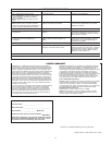
I
nterconnected units can provide earlier warning of fire than stand-alone
units, especially if a fire starts in a remote area of the dwelling. If any unit
i
n the series senses smoke, all units will alarm. To determine which Alarm
i
nitiated an alarm, see table:
During an Alarm:
On Initiating Alarm(s) Red LED(s) flashes (flash) rapidly
On All Other Alarms Red LED is Off
A
fter an Alarm (Latching):
O
n Initiating Alarm(s) Red LED(s) On for 2 seconds/Off for 2 seconds
O
n All Other Alarms Green LED(s) On, Red LED(s) Off
C
ompatible Interconnected Units
I
nterconnect units within a single family residence only. Otherwise all
households will experience unwanted alarms when you test any unit
in the series. Interconnected units will only work if they are wired to
c
ompatible units and all requirements are met. This unit is designed to
be compatible with:
BRK Electronics
®
Smoke Alarm Models 9120,
9
120B, SC9120B, 7010, 7010B, 4120, 4120B, 4120SB, 4919, 2002RAC,
1
00S, 5919, 5919TH;
B
RK Electronics
®
H
eat Alarm Models HD6135F,
HD6135FB; BRK Electronics
®
CO Alarm Models CO5120BN,
CO5120PDBN; Smoke/CO Alarm Model SC6120B, SC7010BV,
S
C7010B; and
F
irst Alert
®
S
moke Alarm Models SA4120, SA4120B,
SA4121B, SA4919B, SA100B.
Interconnected units must meet ALL of the following requirements:
• A maximum of 18 compatible units may be interconnected
(Maximum of 12 Smoke Alarms).
• The same fuse or circuit breaker must power all interconnected
units.
• The total length of wire interconnecting the units should be
less than 1000 feet (300 meters). This type of wire is commonly
available at Hardware and Electrical Supply stores.
• All wiring must conform to all local electrical codes and NFPA 70
(NEC). Refer to NFPA 72, NFPA 101, and/or your local building
code for further connection requirements.
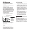
}
}
A. Unswitched 120VAC
60 Hz source
B. To additional units; Maximum = 18 total
(Maximum 12 Smoke Alarms)
1. Alarm
2. Ceiling or Wall
3. Power Connector
4. Wire Nut
5. Junction Box
6. Neutral Wire (Wht)
7. Interconnect Wire
(Orange)
8.
Hot Wir
e (Blk)