


11
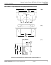
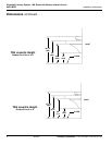
Express® Lavatory System - MG Series with Battery Infrared Control
Installation Instructions MG-2/BIR3
Bradley Corporation • 215-1510 Rev. D; ECN 07-815 8/23/07
Installation Instructions continued . . .
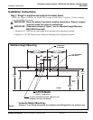
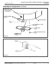
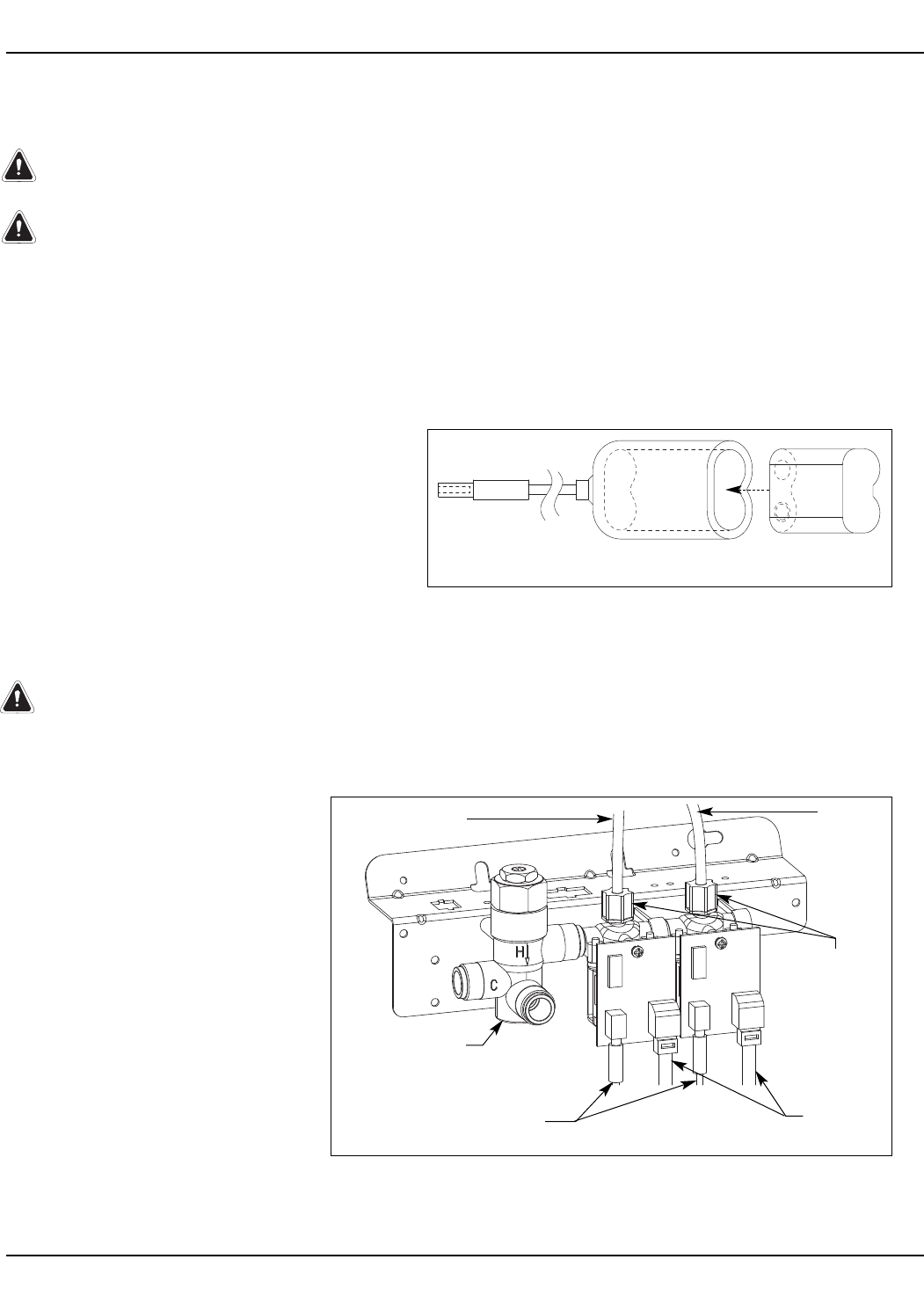
Step 7: Connecting electrical and supply tubing
WARNING: The MG-2/BIR3 must be connected to the 6 VDC battery. Connection to 110
VAC may cause personal injury and/or damage to electronics. Connection of leads
other than shown may cause permanent sensor damage.
CAUTION: To avoid activating the sprayhead valve, make sure to connect the sensor
cable plugs to the circuit board before inserting the batteries into the battery holder.
If the cable is connected or disconnected while the batteries are installed, the station
will activate and continue running for 75 seconds.
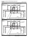
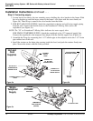
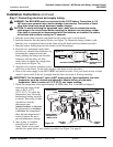
1. Snap the sensor plugs from the sprayhead into the proper valve’s circuit board.
2. Insert the batteries into the battery holders (see Figure 7a). Mount the battery holders (with
batteries) in a convenient location on the frame using the hook-and-loop fastener provided.
3. Snap the battery holder plugs into the female circuit board plugs.
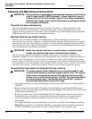
4. Insert the two sprayhead supply tubes
into the two solenoid tube connectors by
loosening the compression nut and
firmly pushing the tubing into the tube
connector until the tubes are fully
seated, then re-tighten the compression
nut by hand (see Figure 7b).
5. Align the valve bracket mounting screws
with slots on the frame. Let the valve bracket slide down to lock into place.
6. Turn on the water supply to the MG-2/BIR3 and check for leaks. Pass your hand in front of each
station’s sensor until all the air is purged from the lines and water is flowing smoothly.
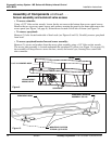
IMPORTANT: The Vernatherm™ valve is NOT factory-preset. Upon installation, the valve
temperature must be checked and adjusted to ensure delivery of safe water
temperature. Water in excess of 110°F (43°C) may cause scalding.
7. Check the temperature when approximately1.0 GPM water flow is reached and adjust if
necessary (the range of the
valve is 95°F–115°F
(35°C–43°C). To adjust the
temperature, first loosen the
temperature locking nut with
a wrench. Then using a blade
screwdriver, turn the
adjustment stem
counterclockwise to increase
the temperature or clockwise
to decrease the temperature.
Once desired temperature is
reached, tighten the nut to
prevent temperature change.
8. After testing is complete,
reinstall access panel to
frame. Fasten access panel
with the five panel screws and washers provided (see Figure 3 on page 8).
Figure 7b
RED
SUPPLY
TUBE
GREEN SUPPLY
TUBE
BATTERY
CABLE
SENSOR
CABLE
Figure 7a
BATTERY HOLDER (S83-177)
6-volt LITHIUM BATTERY
(261-010)
COMPRESSION
NUT (110-231)
VERNATHERM™
THERMOSTATIC
MIXING VALVE