


Express® Lavatory System - MG Series with Battery Infrared Control
MG-2/BIR3 Installation Instructions
10 8/23/07 Bradley Corporation • 215-1510 Rev. D; ECN 07-815
Installation Instructions continued . . .
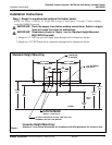
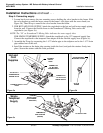
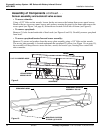
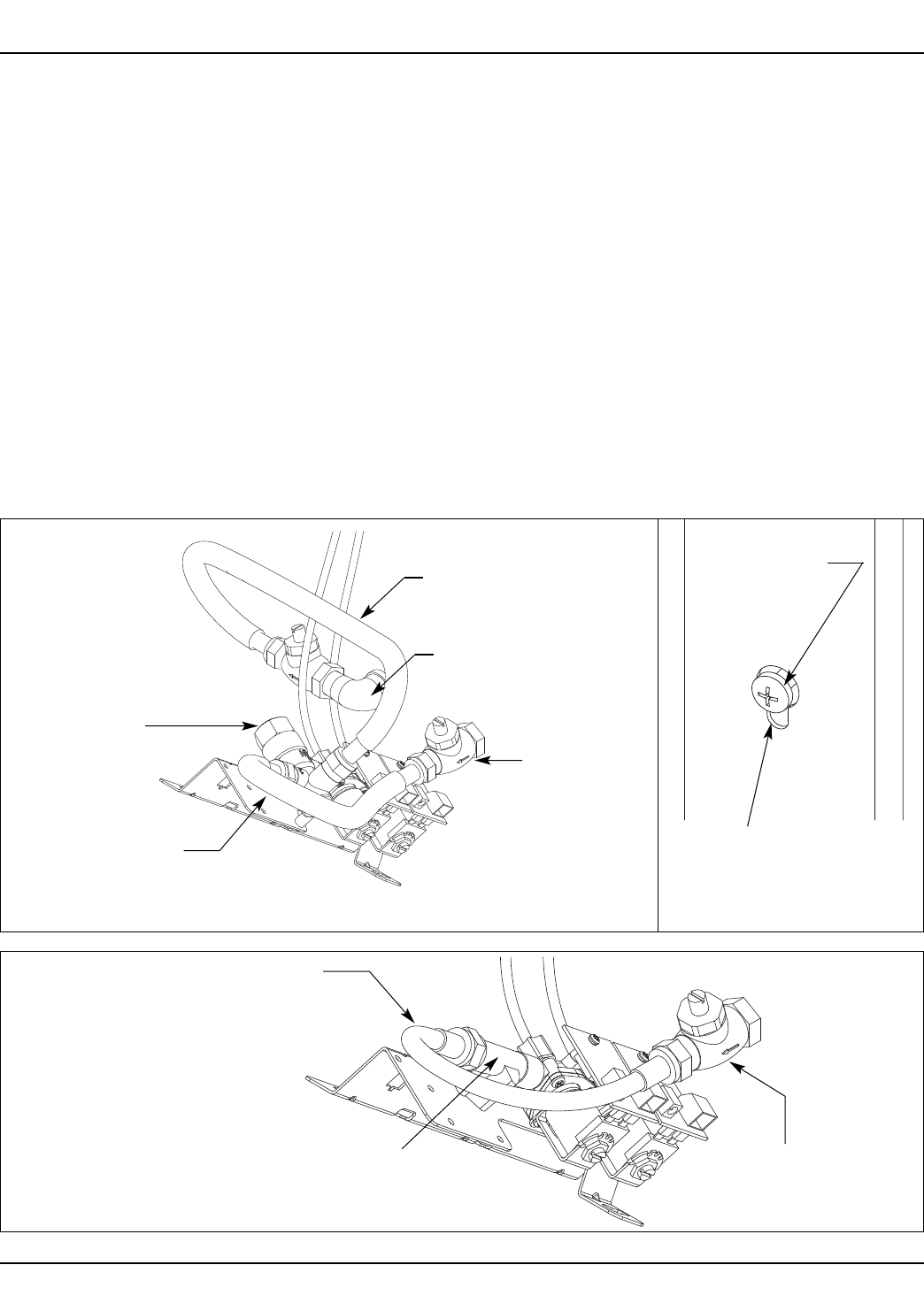
Step 5: Connecting supply
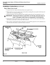
1. Loosen but do not remove the two mounting screws holding the valve bracket to the frame. Slide
the valve bracket up until the larger cutout in the frame’s slot aligns with the screw head (see
Figure 5b). Then lift up to remove the valve bracket from the frame.
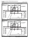
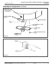
2. FOR HOT AND COLD SUPPLY: Attach the stop/check to the hot and cold water supply piping
from the wall. Connect the flexible hoses to the Vernatherm™ Mixing Valve and to the
stop/checks (see Figure 5a).
NOTE: The “H” on Vernatherm™ Mixing Valve indicates hot water supply inlet.
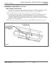
FOR SINGLE TEMPERED SUPPLY: Attach the stop/check to the 1/2" tempered supply line.
Connect the stop/check to the tempered line adapter with the flexible supply hose (Figure 5c).
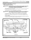
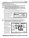
3. Assemble the P-trap by connecting the 1-1/2" tubular pipe to the tailpiece and to the 1-1/2" drain
pipe stubbed out of the wall.
4. Install the strainer on the drain plug opening inside the bowl, and push the strainer firmly into
place. Secure the stainer with the screw provided.
Figure 5c
FLEXIBLE
SUPPLY HOSE
(TO SOLENOID
BRACKET)
TO SUPPLY LINE
Figure 5a
FLEXIBLE SUPPLY
HOSE
Vernatherm™
THERMOSTATIC
MIXING VALVE
FLEXIBLE
SUPPLY
HOSE
CONNECT TO
1/2" NPT HOT
WATER SUPPLY
CONNECT TO
1/2" NPT COLD
WATER SUPPLY
TEMPERED
LINE ADAPTER
(S39-685)
Figure 5b
SLOT IN
FRAME
VALVE BRACKET
MOUNTING SCREW
Hot and
Cold
Supplies
Single
Tempered
Supply