


9
General Information continued-
SACRIFICIAL ANODES — Two sacrificial anode rods have been installed in the tank head to extend tank life.
The anode rods should be inspected annually to determine the amount of sacrificial decay and replaced when
necessary to prolong tank life. The permanent removal of these anodes, for any reason, will nullify the warranty.
Water conditions in your area will influence the time interval for inspection and replacement of the anode rod. The
use of a water softener may increase the speed of anode consumption. More frequent inspection of the anode is
needed when using softened (or phosphate treated) water. Contact the plumbing professional who installed the water
heater or the manufacturer, listed on the rating plate, for anode replacement information.
TEMPERATURE AND PRESSURE RELIEF VALVE
WARNING
Keep clear of the combination temperature and pressure relief valve discharge line outlet. The discharge may
be hot enough to cause scald injury. The water is under pressure and may splash.
For protection against excessive temperatures and pressure, install temperature and pressure protective equipment
required by local codes, but not less than a combination temperature and pressure relief valve certified by a
nationally recognized testing laboratory that maintains periodic inspection of production of listed equipment or
materials as meeting the requirements of the Standard for Relief Valves and Automatic Gas Shutoff Devices for Hot
Water Supply Systems, ANSI Z21.22 and the Standard CAN1-4.4 Temperature, Pressure, Temperature and Pressure
Relief Valves and Vacuum Relief Valves. The combination temperature and pressure relief valve must be marked
with a maximum set pressure not to exceed the maximum working pressure of the water heater. The combination
temperature and pressure relief valve must also have an hourly rated temperature steam BTU discharge capacity not
less than the hourly rating of the water heater/storage unit. The supplied combination temperature and pressure
relief valve, when properly installed and unrestricted, will discharge the maximum input produced by a 240°F
(115°C) collector supply temperature. A lower collector supply temperature will reduce the input required to be
discharged in the event of excessive potable water temperatures.
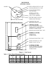
Install the combination temperature and pressure relief valve into the opening provided and marked for this purpose
on the water heater/storage unit.
Some models may already be equipped or supplied with a combination temperature and pressure relief valve.
Verify that the combination temperature and pressure relief valve complies with local codes. If the combination
temperature and pressure relief valve does not comply with local codes, replace it with one that does.
Install a discharge line so that water discharged from the combination temperature and pressure relief valve will
exit within six (6) inches above, or any distance below the structural floor and cannot contact any live electrical
part. The discharge line is to be installed to allow for complete drainage of both the temperature and pressure relief
valve and the discharge line. The discharge opening must not be subjected to blockage or freezing. DO NOT
thread, plug, or cap the discharge line. It is recommended that a minimum clearance of four (4) inches be provided
on the side of the water heater/storage unit for servicing and maintenance of the combination temperature and
pressure relief valve
Do not place a valve between the combination temperature and pressure relief valve and the tank!