


20
SECTION VII
OPERATING INSTRUCTIONS
SYSTEM START-UP
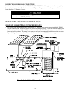
Follow solar collector installation instructions to place collector in operation. Ensure that solar fluid flow operation
is established for the installed system.
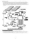
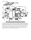
SEQUENCE OF HEATING OPERATIONS -SOLAR AND ELECTRIC BACKUP
1. The solar controller senses a large enough temperature difference between the lower tank and the solar collector
to transfer heat into the tank.
a. The solar controller activates a circulator/pump to flow fluid through the heat exchanger and solar collector,
transferring heat into the storage tank until the temperature difference is significantly reduced.
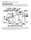
2. The upper element thermostat senses that the water temperature stored in the upper portion of the tank drops
below the desired setting.
a. The upper element is energized to heat stored water to the desired temperature. Once the water in the upper
tank is heated to the desired temperature, the element is de-energized.
3. The lower element thermostat senses that the water temperature stored above the solar heat exchanger drops
below the desired setting.
a. The lower element is energized to heat stored water to the desired temperature. Once the water in the lower
tank is heated to the desired temperature, the element is de-energized.
WATER TEMPERATURE ADJUSTMENT
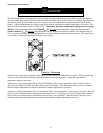
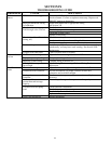
Table 7 details the approximate relationship of water temperature and time with regard to scald injury and may be
used as a guide in determining the safest water temperature for your applications.
can cause severe burns
are at hi
g
hest risk of bein
g
Children, disabled and elderl
y
instantl
y
or death from scalds.
Water tem
p
erature over 125°F
Feel water before bathin
g
or
before settin
g
tem
p
erature
available.
showerin
g
.
Tem
p
erature limitin
g
valves are
Review this instruction manual
at water heater.
scalded.
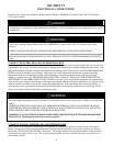
Figure 9 – Scald Warning
WARNING
SCALDING
This water heater can deliver scalding temperature water at any faucet in the system. Be careful whenever
using hot water to avoid scalding injury. By setting the thermostat on this water heater to obtain an
increased water temperature, you may create the potential for scald injury. To protect against injury, you
should install an ASSE approved mixing valve (a device to limit the temperature of water to protect against
scald injury via mixing hot and cold water supply) in the water system. This valve will reduce point of
discharge temperature in branch supply lines. This water heater was shipped with an ASSE approved
mixing valve. Install this valve according to the directions in the mixing device container. DO NOT
OPERATE THIS WATER HEATER A MIXING DEVICE. If this water heater was shipped without a
mixing device, contact the manufacturer.
APPROXIMATE
TIME/TEMPERATURE
RELATIONSHIPS IN SCALDS
120°F More than 5 minutes
125°F 1 ½ to 2 minutes
130°F About 30 seconds
135°F About 10 seconds
140°F Less than 5 seconds
145°F Less than 3 seconds
150°F About 1 ½ seconds
155°F About 1 second
Table 7 – Scald Relationshi
p
s