


19
Electrical Connections continued-
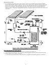
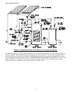
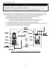
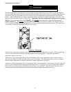
Refer to Figure 8 for connecting the thermistor and pressing it against the tank. This figure illustrates the opening
under the upper control cover. While the lower control location does not hold a thermostat, the process is the same.
1. Positively assure all electrical connections are unpowered whenever removing the control covers.
2. Strip the twisted wire ends and use wire nuts to securely connect the thermistor wires.
3. Pull the insulation material away slightly from the water heater tank.
4. Slide the thermistor between the insulation and the water heater tank.
a. The upper tank thermistor should be inserted as shown in the lower right hand corner.
b. The lower tank thermistor should be inserted half way up on the right hand side.
5. Verify that the insulation provides enough pressure to hold the thermistor in place.
6. To assure that the thermistor does not move, apply a small amount of high temperature silicon sealant in the
insulation gap produced where the thermistor has been inserted.
7. Return power to the water heater once the covers are in place.
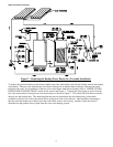
Figure 8 – Wiring and Placement for the Solar Control Thermistor
NOTICE
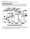
A solar control and thermistors are not supplied with this water heater. The Tekmar 156, when installed according
to manufacturer’s instructions, is an acceptable controller. Other solar controller manufacturers such as Steca and
Resol provide controllers appropriate for use with this water heater.
Thermistors are not included with the water heater. Thermistors must be purchased with the solar controller to
ensure capability with the selected control. Contact the solar controller manufacturer for details.