


Anti-frost heaters do not operate
1) Are the ceramic anti-frost heaters operating normally ?
2) Is the frost sensor switch operating normally ?
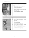
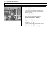
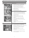
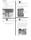
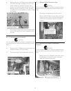
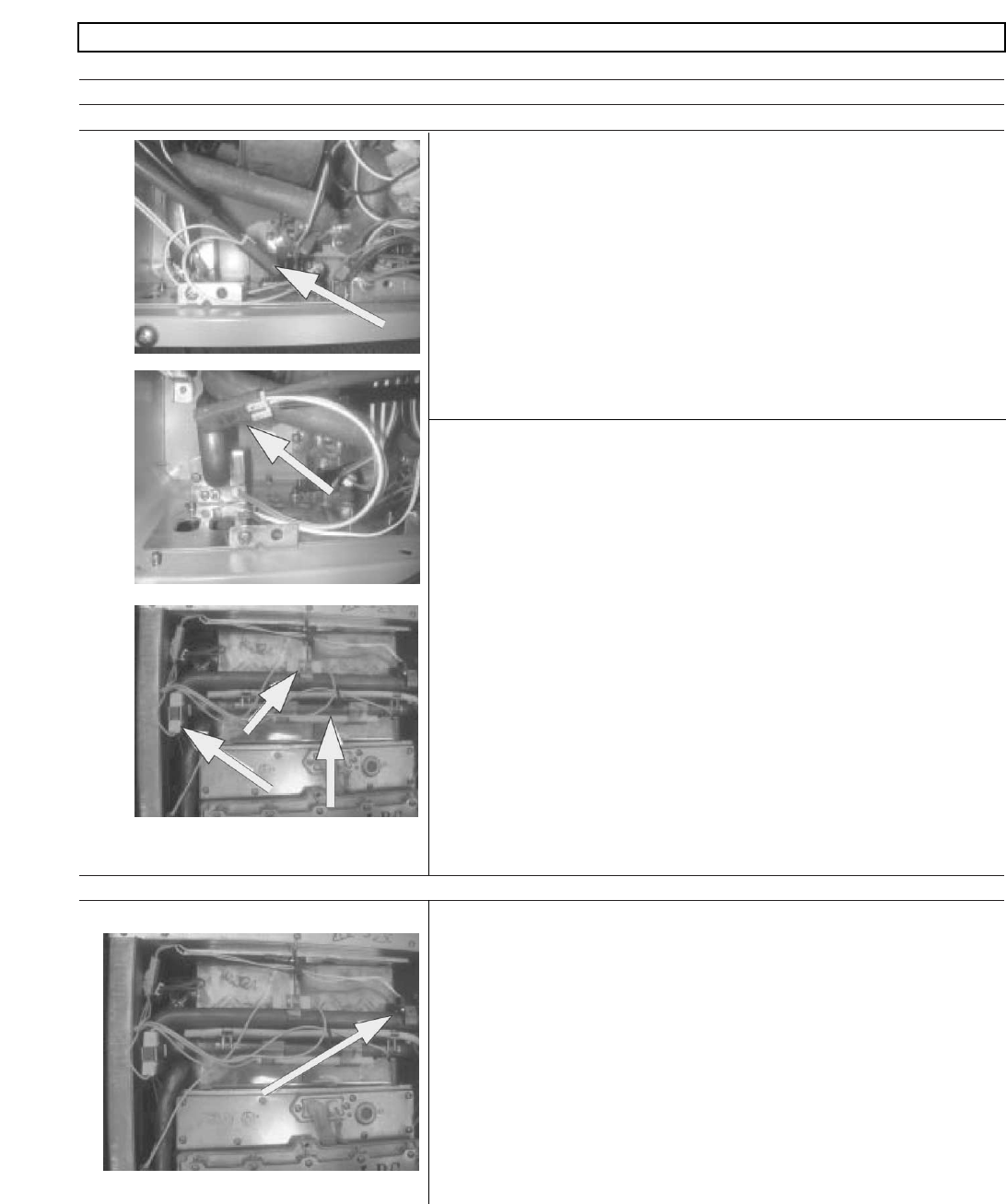
a. # Disconnect connector F4, and measure the
resistance of the heater mounted in the water
flow control valve, these are white wires.
Disconnect connector F5, and measure the
resistance of the heater in the outlet line
connector See connectors in the first and second
picture t o the left.
Normal: 348
~
375 Ω
If normal, proceed to b.
Faulty: Replace defective element.
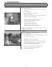
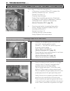
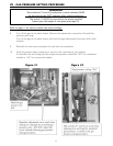
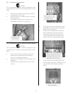
b. # Take an ohm meter and read resistance across
the heater on the face of the heat exchanger. The
resistance across this element is listed below. See
third picture to the left for location of this element.
These are white wires.
Normal: 100
~
11 0 Ω
If normal, proceed to check item 2 below.
Faulty: Replace defective anti frost heater
assembly.
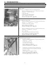
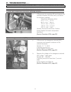
c. Check resistance of the two heat exchanger
outlet line heater elements, as shown in the
third picture to the left. Check across each heater
independently.
Normal: 33
~
39 Ω
Faulty: Replace defective anti frost heater
assembly.
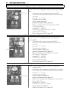
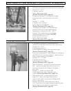
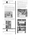
a. # Disconnect connector F2, and measure the
resistance through this switch, measure when
atmospheric temperature is 37°F + or – 3°F. (See Note)
See drawing to left for location of this bimetal
switch. These are white wires to this switch.
Normal: Less than 1 Ω
If normal, check wiring harness for defects.
(100 volts AC)
Faulty: Replace the frost sensing bimetal switch.
Note: If the atmospheric temperature is too high,
cool the switch with ice.
45
BEFORE CARRYING OUT CHECKS MARKED WITH A # SIGN, DISCONNECT THE POWER SUPPLY.