


34
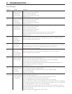
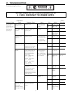
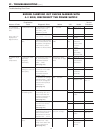
Nature of Fault
Examination
Point Diagnostic Point Values Y/N Action
Service
Procedure
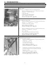
C. Combustion
occurs, but flame
fails.
Error code "12"
displayed on
digital monitor.
1. Check flame rod.
2. Check ground
wire.
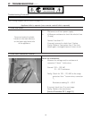
1. Measure the voltage
between flame rod
terminal C
1
and
appliance ground.
2. Check to ensure flame
rod bracket is not loose.
Check for faulty ground
wire connections at unit,
receptacle, and ground
rod to home, and for
broken or shorted wires.
5
~
150 VAC
Is it secure?
Are connections
OK?
Yes
No
Yes
No
Yes
No
Go to C-1-2
Replace PCB
Go to C-2
Replace/
rectify
Check for
other causes
of flame
failure.
Replace or
repair
grounding
circuit to unit.
IGI – 2
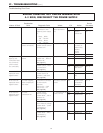
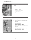
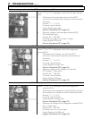
D. Cannot adjust
water
temperature.
1. Check hot water
thermistor.
(outgoing
thermistor)
# Disconnect connector
B
5
and measure the
resistance between
white
~
white.
(See page 43)
Resistance values
match table on page
#43
Yes
No
Go to D – 2
Replace water
temperature
thermistor.
IGI – 6
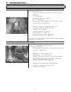
2. Check
changeover solenoid
valve (SV3).
1. # Disconnect
connector E from PCB
and measure the
resistance between
brown
~
black.
2. Measure the voltage
between brown
~
black
wire of the changeover
solenoid valve (SV3) at
connector E.
(See page 41)
1.7
~
2.1KΩ
80
~
100 VDC
Yes
No
Yes
No
Go to D – 2-2
Replace
manifold
assembly
Go to D – 3
Replace PCB
IGI – 8
IGI – 2
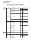
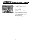
3. Check
modulating valve.
1. # Disconnect
modulating valve at C
2
festoon terminal and
measure resistance at
solenoid terminals.
(See page 44)
2. Measure the voltage
between two harness
terminals at C
2
.
(See page 44)
3. Check whether the
manifold pressure alters
when remote control
temperature is altered
between 96°
~
14 0°F.
67
~
81Ω
2
~
15 VDC
Does the manifold
pressure change?
Yes
No
Yes
No
Yes
No
Go to D – 3-2
replace gas
valve
Go to D – 3-3
Replace PCB
Go to D – 4
Replace gas
valve
IGI – 9
IGI – 2
IGI – 9
4. Check water flow-
servo.
1, # Measure resistance
between red
~
blue
wires of the water flow
servo connector B
2
.
(See page 44)
22
~
26Ω Yes
No
Go to D – 4-2
Replace water
flow servo
sensor.
IGI – 3
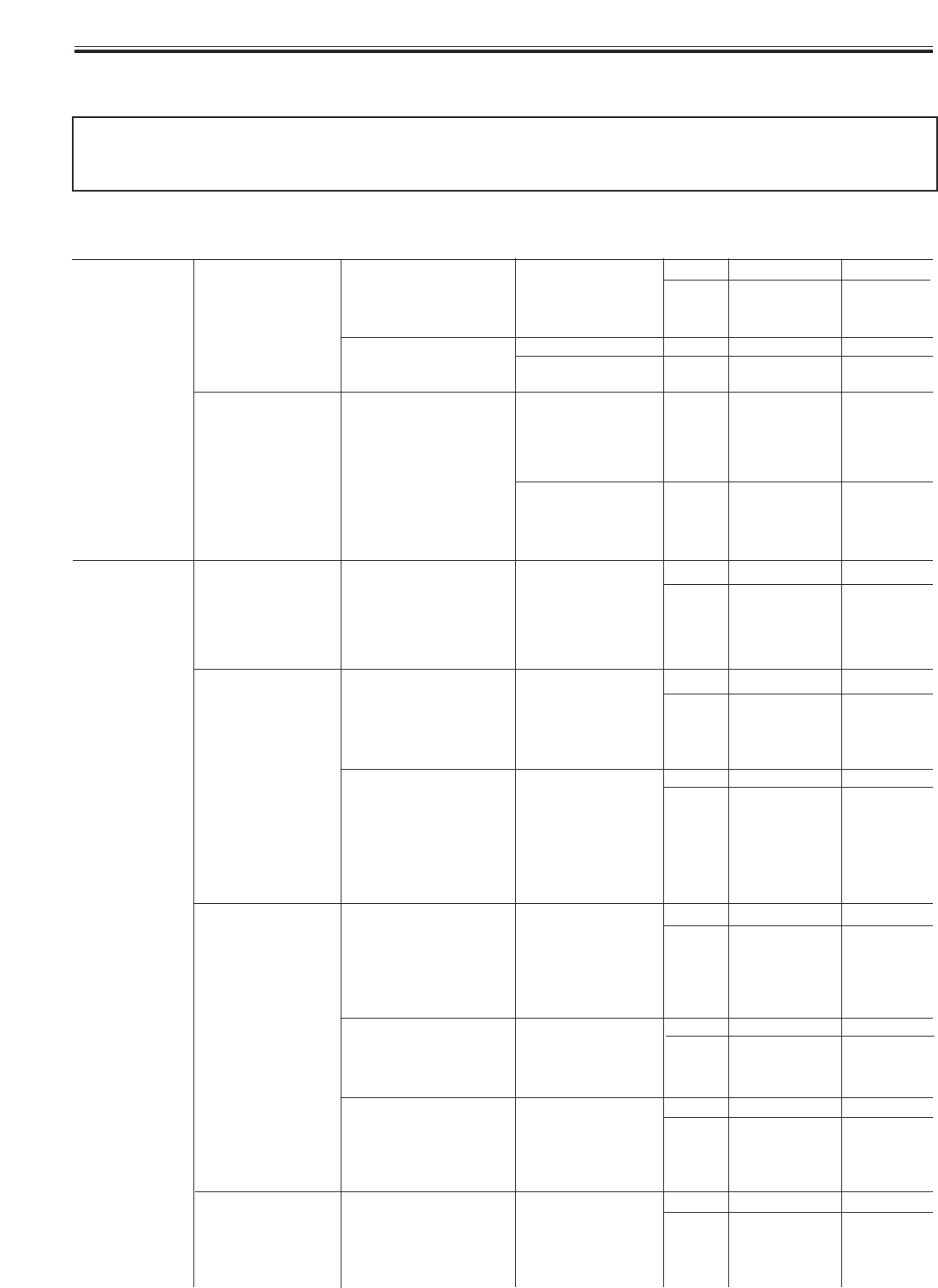
VI - TROUBLESHOOTING (cont.)
Troubleshooting Flow Chart
BEFORE CARRYING OUT CHECKS MARKED WITH
A # SIGN, DISCONNECT THE POWER SUPPLY.