


28
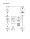
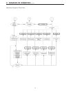
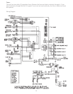
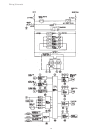
VI - TROUBLESHOOTING (cont.)
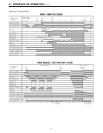
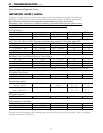
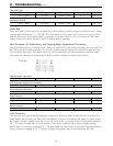
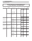
Thermal Fuse:
Wire color Voltage Resistance Connector # Pin #’s
Red ~ Red 100 VAC Below 1 ohm B ~ C B6 ~ C1
Overheat Switch:
Red ~ Red 100 VAC Below 1 ohm B ~ C B6 ~ C1
Flame Rod:
Place one lead of your meter to the flame rod and the other to earth or ground. With the unit running
you should read between 5 ~ 150 VAC. Set your meter to the µ amp scale, series your meter in line
with the flame rod. You should read1µ or greater for proper flame circuit. In the event of low flame
circuit remove the flame rod and check for carbon and/or damage.
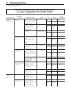
Heat Exchanger, Air Temperature, and Outgoing Water Temperature Thermistors:
Check all thermistors by inserting meter leads into each end of the thermistor plug. Set your meter to
the 20K scale and read resistance. You should be able to apply heat to the thermistor bulb and see
the resistance decrease. Then apply some ice to the thermistor and the resistance should increase.
See below for examples of temperatures and resistance reading at those temperatures.
Example: 59ºF = 11.4 ~ 14K
86ºF = 6.4 ~ 7.8K
113ºF = 3.6 ~ 4.5K
140ºF = 2.2 ~ 2.7K
221ºF = 0.6 ~ 0.8K
Outgoing Water Thermistor:
White ~ White N/A See example above B4 B3 ~ B4
Heat Exchanger Temperature Thermistor:
White ~ Pink N/A See example above B5 B3 ~ B12
Air Temperature Thermistor:
White ~ Orange N/A see example above B1 B2 ~ B11
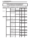
Surge Protector:
Black ~ White 108 ~ 132 VAC N/A Surge Protector D
1
1 ~ 3
Blue ~ Brown 108 ~ 132 VAC N/A Surge Protector D
2
1 ~ 2
Remote Controls:
Terminals D
1
10 ~ 13 VDC digital 1.5K ~ 1.9K ohms H 1 ~ 3
Frost Protection:
This unit has four frost protection heaters mounted at different points inside the unit to protect the
water heater from freeze ups. There are two heaters located on the outlet hot water line next to the
thermistor. Using a voltage meter set on the 200 ohm scale, you should have a resistance reading of
26 ~ 30 ohms through each of these heaters. The heater located on the heat exchanger piping
should have a resistance reading of 81 ~ 86 ohms and the one located in the water flow sensor valve
has a resistance reading of 16
~
19 ohms. Voltage throughout this circuit should be 120 VAC.