


IV - SAFETY DEVICE FUNCTION
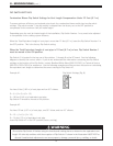
Flame Failure
Situated to the right of the burner in the front of the combustion chamber, the flame rod monitors the
combustion process. This sensor monitors the flame intensity, while the PCB compares this signal to
the feed back signal from the combustion fan motor, water flow control, and gas flow through the POV
valve. If any one of the feedback signals are incorrect, the unit will shut off, preventing discharge of
gas to the burner.
Over Heat Protection Device
Also referred to as an Over Heat Switch. This device is fitted to a bend section at the inlet to the heat
exchanger. If the flame remains on to the burner after the tap is closed and the water temperature
inside the heat exchanger reaches 194 ° F, a 12 volt DC bi-metal cut-off switch will shut off the gas
supply to the solenoids.
No Water
Should the incoming water flow become restricted or stop, the water flow sensor will cease to send a
magnetic pulse signal to the PCB, in turn preventing gas to flow into the combustion chamber. If you
have restricted flow, first check to ensure the inline water filter is not clogged.
Thermal Fuse (Non-Resettable)
Wrapped around the entire surface of the heat exchanger you will find a thermal fuse. This device
activates in the event of excessive heat echanger temperatures, or the temperature outside the heat
exchanger reaches 264 °F. If the thermal fuse melts, it breaks an electronic circuit which in turn shuts
off the power supply to the gas solenoids, deactivating the unit.
Combustion Fan Revolution Check
The combustion fan rpm’s are continually monitored by a magnetic pulse generator connected to the
PCB. If the fan revolutions deviate from the speed required for complete combustion, a signal is sent
to the PCB and the revolutions adjust accordingly. (If not the unit deactivates)
Automatic Frost Protection
When the temperature inside the appliance drops below 37°F , the frost sensing device inside the
appliance activates the anti-frost heaters to prevent the water inside the unit from freezing. The anti-
frost heaters remain ON until the temperature inside the appliance rises to 57°F. There are four (16)
watt anti-frost heaters located at various points throughout the main water flow area of the appliance.
The unit also incorporates the ability to fire for (3) seconds in the event the anti-frost heaters can not
keep the water temperature from dropping below 37°F. This unique feature will heat the water in the
lines inside the appliance back up to 57°F. Both of the above features function as long as the unit
has power and gas. There is an optional freeze protection system that can be added to the unit’s
piping. Refer to the auto drain down diagram in the product installation instructions for instructions
on how to install the optional freeze protection in the event of a power failure.
17