


14
Venting continued-
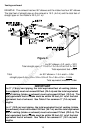
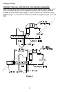
This water heater is a power direct vented appliance and is designed to intake
and exhaust its products of combustion through 3” (7.6 cm) or 4” (10.2 cm)
diameter Schedule 40 PVC pipe to the outdoors. This water heater may intake
and exhaust either through the wall or vertically through the roof. Use a 3” (7.6
cm) to 4” (10.2 cm) reducer to connect to the intake and outlet when using 4”
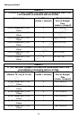
(10.2 cm) PVC. Table 2 lists the maximum intake and exhaust lengths for this
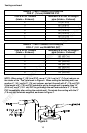
water heater using 3” (7.6 cm) PVC. If possible, locate the water heater so that
the venting length and number of elbows are kept to the minimum distance
necessary to reach the outside. If the installation requires venting lengths that
exceed the lengths listed for 3” (7.6 cm) PVC in Table 2, then use 4” (10.2 cm)
PVC for the vent connector. Table 3 lists the venting distances allowed with 4”
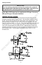
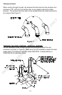
(10.2 cm) diameter PVC pipe. When venting with 4” (10.2 cm) PVC, use a 4”
(10.2 cm) to 3” (7.6 cm) reducer to exit through the building wall with 3” (7.6 cm)
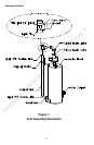
PVC. Use the 3” (7.6 cm) vent terminal supplied with the water heater to
terminate on the outside of the building. If the length of the 3” (7.6 cm) PVC
needed to go through the wall is greater than 14” (35.5 cm), use 4” (10.2 cm)
PVC to go through the wall and reduce to 3” (7.6 cm) PVC immediately after
exiting the outside wall. Refer to the venting illustrations on the following pages.
Make sure the vent pipe terminal elbow fittings are at least 1” (2.5 cm) away from
the edge of the wall.
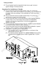
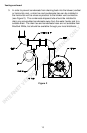
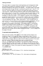
To calculate total equivalent feet
Add up the total number of 90° elbows on the intake and the exhaust, and
multiply by 5 feet (1.5 m) (each 90° elbow is equivalent to 5 feet (1.5 m) of
straight pipe). To this number add the total number of feet of straight pipe on the
intake and the exhaust. This sum (total of all 90° elbows at 5 feet (1.5 m) each,
plus total number of feet of straight pipe) must not exceed 80 feet
(24.4 m). All elbows must be included in the calculation except those on the
extreme ends of the intake and exhaust. 45° elbows may also be used. When
using 45° elbows, take the total number of 45° elbows on the intake and exhaust
and multiply by 2 1/2 feet (.76 m) (each 45° elbow is equivalent to 2 1/2 feet (.76
m) of straight pipe).
Total equivalent feet=
(# of 90° elbows x 5) + (# of 45° elbows x 2 1/2) + (total feet of straight pipe)
Total equivalent meters=
(# of 90° elbows x 1.5) + (# of 45° elbows x .76) + (total meters of straight pipe)
INTERNET VERSION FOR REFERENCE ONLY