


10
Venting continued-
Venting Installation Instructions For Supplied Intake Venting:
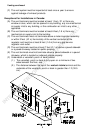
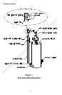
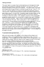
1. Refer to Figure 1, “Vent Assembly Illustration” to install intake venting
as described below.
2. Insert one end of the Vertical Pipe into Metal Boot on the lower
backside of the water heater.
3. Slide the Support Bracket over the Vertical Pipe, but do not fasten to
the Jacket Head.
4. Position the Intake Tee on top of the Vertical Pipe so that the short
straight section of the tee faces the Blower Intake Collar, and the
curve of the tee faces upward. Proper orientation of the curved
section of the tee is critical. Be sure it is facing upward. Refer
to “This End Up” label on Intake Tee.
5. Slide the Rubber Intake Elbow over the Blower Intake Collar and over
the short straight section of the Intake Tee.
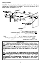
6. Using a level to ensure that the Vertical Pipe is straight up and down,
secure the Vertical Pipe to the Jacket Head using the Support
Bracket and three (3) self-drilling screws provided. NOTE: Correct
vertical positioning of the Vertical Pipe is Important.
7. After securing the Vertical Pipe to the Jacket Head with the Support
Bracket, tighten the clamps on the Rubber Intake Elbow.
8. Using the RTV sealant provided, place a bead of RTV around the
Vertical Pipe at the Metal Boot location, and at the Intake Tee
location. Smooth out the RTV to provide a seal at both locations.
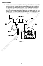
9. Two 90° end terminal elbows are supplied. These must be installed at
the extreme ends of the intake and exhaust venting outside the
building. The end terminal with the external screen must be installed
on the intake vent as shown in Figure 7.
10. Proceed as necessary to complete the venting installation as
described in the venting section of this manual.
INTERNET VERSION FOR REFERENCE ONLY