


11
Water connections continued-
If this water heater is installed in a closed water supply system, such as the one
having a back-flow preventer in the cold water supply, provisions shall be made
to control thermal expansion. DO NOT operate this water heater in a closed
system without provisions for controlling thermal expansion. Your water
supplier or local plumbing inspector should be contacted on how to control this
situation.
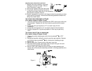
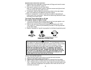
After installation of the water lines, open the main water supply valve and fill the
water heater. While the water heater is filling, open several hot water faucets
to allow air to escape from the water system. When a steady stream of water
flows through the faucets, close them and check all water connections for
possible leaks. NEVER OPERATE THE WATER HEATER WITHOUT FIRST
BEING CERTAIN IT IS FILLED WITH WATER.
WARNING
For protection against excessive temperatures and pressure, install temperature and
pressure protective equipment required by local codes, but not less than a
combination temperature and pressure relief valve certified by a nationally
recognized testing laboratory that maintains periodic inspection of production of
listed equipment or materials as meeting the requirements of the Standard for Relief
Valves and Automatic Gas Shutoff Devices for Hot Water Supply Systems, ANSI
Z21.22 or the Standard CAN1-4.4. Temperature and Pressure and the Standard
CAN1-4.4, Temperature, Pressure, Temperature and Pressure Relief Valves and
Vacuum Relief Valves. The combination temperature and pressure relief valve shall
be marked with a maximum set pressure not to exceed the maximum working
pressure of the water heater. The combination temperature and pressure relief
valve shall also have an hourly rated temperature steam BTU discharge capacity not
less than the hourly rating of the water heater.
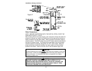
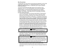
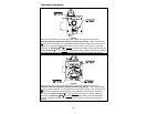
Install the combination temperature and pressure relief valve into the opening
provided and marked for this purpose on the water heater.
Note: Some models may already be equipped or supplied with a combination
temperature and pressure relief valve. Verify that the combination temperature and
pressure relief valve complies with local codes. If the combination temperature and
pressure relief valve does not comply with local codes, replace it with one that does.
Follow the installation instructions above on this page.
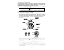
Install a discharge line so that water discharged from the combination temperature
and pressure relief valve will exit within six (6) inches (15.2 cm) above, or any
distance below the structural floor and cannot contact any live electrical part. The
discharge line is to be installed to allow for complete drainage of both the
combination temperature and pressure relief valve and the discharge line. The
discharge opening must not be subjected to blockage or freezing. DO NOT thread,
plug or cap the discharge line. It is recommended that a minimum clearance of four
(4) inches (10.2 cm) be provided on the side of the water heater for servicing and
maintenance of the combination temperature and pressure relief valve.
Do not place a valve between the combination temperature and pressure relief valve
and the tank.