


SERVICE PROCEDURE D24-IV
M
ain Burner & Pilot
Removal and Inspection
WARNING
Heater components may be HOT when performing the following steps in this procedure.
Take necessary precaution to prevent personal injury.
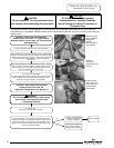
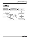
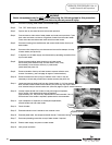
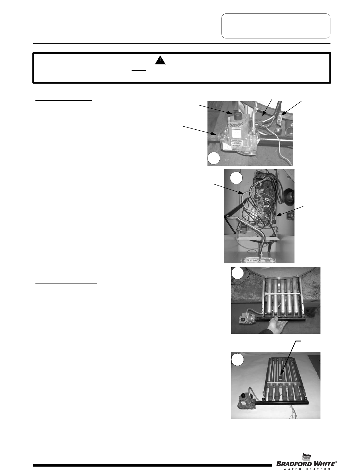
Main Burner Removal
Step 1. Disconnect (un-plug) water heater from
electrical supply.
Step 2. Turn “OFF” gas supply to water heater.
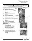
Step 3. Rotate gas valve control knob to the “OFF” position
(see photo 17).
Step 4. Disconnect Gas supply line from the gas valve
(see photo 17).
Step 5. Disconnect wire leads from gas valve
(see photo 17).
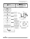
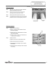
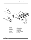
Step 6. Disconnect white flame sense wire & orange ignition
wire from Control Board (see photo 18).
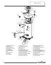
Step 7. Remove the two burner rack mounting screws (see photo 17).
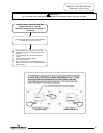
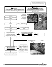
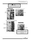
Step 8. Slide complete burner rack out from heater
(see photo 19).
Step 9. To install burner, reverse above procedure.
Step 10. Check for gas leaks and verify proper operation.
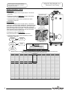
G
as Valve
Control Knob
Gas Supply
Line
G
as Valve
Wire Leads
B
urner Rack
Mounting
Screw
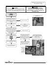
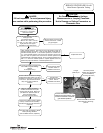
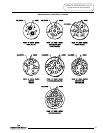
Main Burner Inspection
Step 1. Burner tubes should be free of any flue
scale or other debris. Clean
burner tubes using a stiff brush and/or
shop vac. Burner ports should have uniform
openings. Replacement is recommended for
burners where port area is deteriorated or
other unintended openings are present.
Step 2. Insure pilot shield is in place (see photo 20).
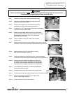
Step 3. Inspect pilot position to insure smooth burner
ignition from pilot flame. Pilot should be
mounted using the two mounting screws through
the burner support bracket resulting in a level
pilot position.
19
Pilot
Shield
17
20
Pilot spark wire
(Orange)
Pilot Flame Sense
Wire (White)
Page 32
18
32