


SERVICE PROCEDURE D24-II
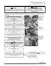
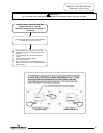
Pilot Operation Testing
CAUTION
Be Careful When Making Voltage
Measurements or Jumping Terminals
Not to Damage or Deform Connectors or
Connector Pins.
DANGER
120 volt exposure. To avoid personal injury,
use caution while performing this procedure.
C
ondition:
Pilot lights, no or low flame signal. Control
Display shows “4” or “62” for Error Codes
(Service Needed). Control continues to spark
until system “Lock Out”.
Main burner will not light.
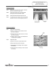
The microamp output of the pilot may be
checked by entering “Service Mode” on the
water heater display and pressing “Select”
until the flame current is shown. The control
must be in the heating mode with the pilot lit
to display a reading. See section on
accessing service mode on the water heater
display.
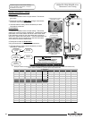
Micro-amp readings
0.000 Micro Amp = Replace control board or pilot if wire is
damaged.
1.0 micro amp or less = Clean pilot flame rod or replace pilot.
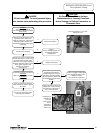
C
heck for loose or damaged ground wire(s)
from gas valve to control board. Check
continuity of wires with ohmeter. Are ground
wires okay?
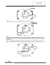
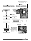
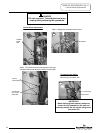
Check for loose or damaged flame sense
l
ead from pilot to Control Board. (see
illustration to the right). Is flame sense lead
okay?
R
epair wire lead
or replace pilot.
Repair ground
wire(s) or replace
as needed.
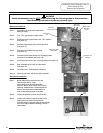
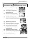
NOTE:
Check continuity of sense lead
to flame rod. If no continuity,
clean pilot flame rod or replace
pilot. Check pilot flame
appearance - if weak check for
clogged pilot orifice, bent pilot
tubing, or low inlet gas
pressure.
(see above illustration)
Y
Y
N
N
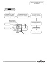
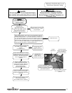
Check venting conditions or negative
pressure.
Is vent system okay?
Correct improper
venting condition.
Refer to Installation
Instructions
N
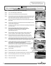
Is heater condensing causing pilot
interruption?
Make sure pilot shield is in place
and not bent or damaged (refer
to section on main burner and
pilot assembly) . Determine
cause for condensing and
correct.
(Possible under sized water
heater or high demand periods.)
Y
Y
N
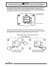
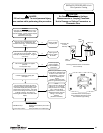
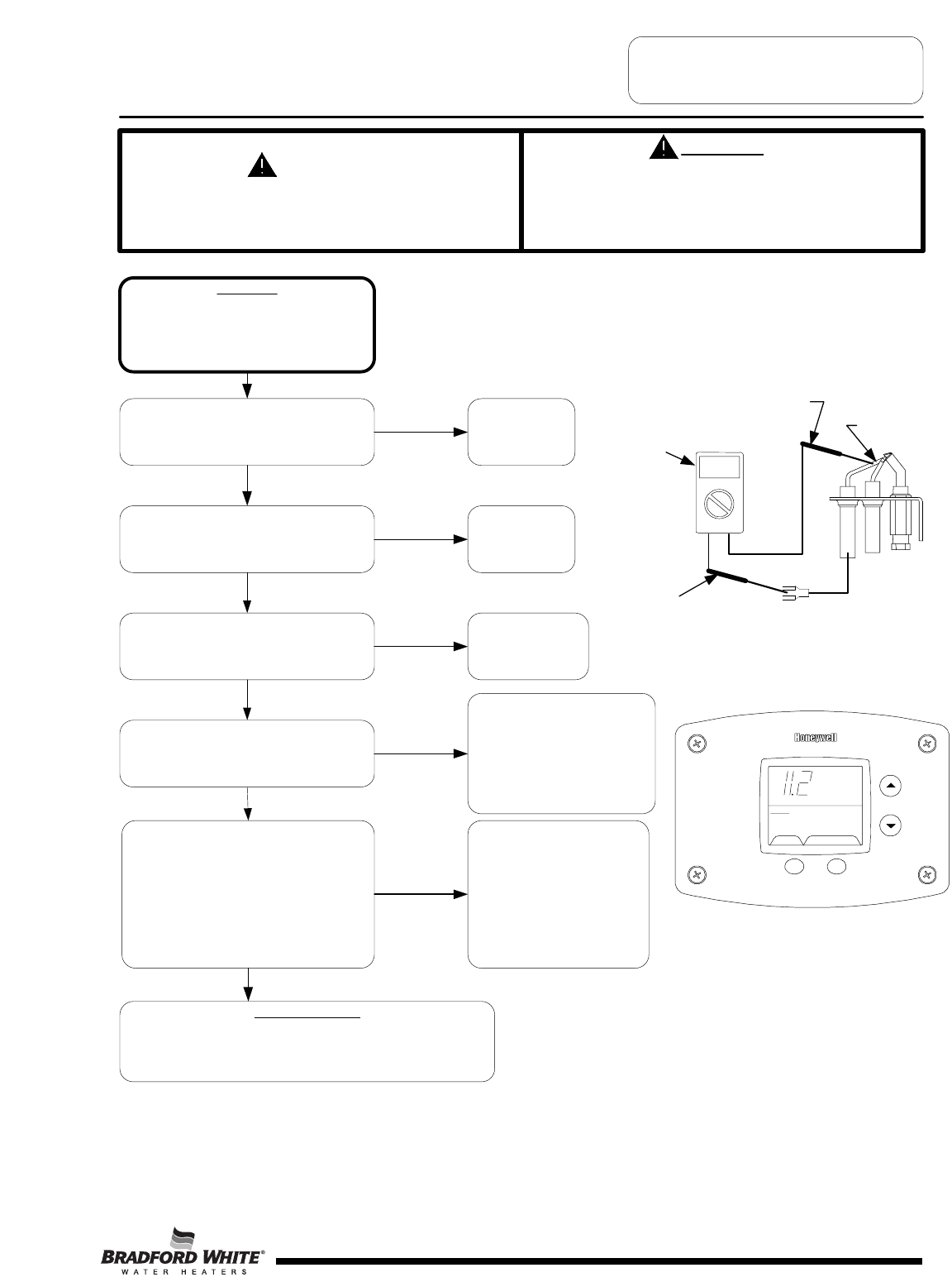
Pilot flame sensor microamp output
shown in display using service mode.
Pilot must be lit to get reading.
Multi-meter set
to check
continuity.
Flame rod
Meter
Probe
Meter
Probe
Checking pilot flame sensor wire and flame
rod for continuity.
Page 29
H
eating
F
lame Current
ȝA
S
ELECT SE
T
Status
Operational
29