


BRADFORD WHITE CORP.
Page 46
SECTION 11.
Maintenance
WARNING
Disconnect all power to the appliance before
attempting any service to the appliance. Contact with
electricity can result in severe injury or death.
11.1 System Maintenance
(yearly, unless otherwise noted)
1. Lubricate the system water-circulating pump, if
required, per the instructions on the pump.
2. If a strainer is employed in a pressure reducing
valve or the piping, clean it every six moBNTHs.
3. Inspect the venting system for obstruction or
leakage at least once a year. Periodically clean the
screens in the vent terminal and combustion air
terminal (when used).
4. Keep the appliance area clear and free from
combustible materials, gasoline, and other
flammable vapors and liquids.
5. If the appliance is not going to be used for
extended periods in locations where freezing
normally occurs, it should be isolated from the
system and completely drained of all water.
6. Low water cutoffs, if installed, should be checked
every year. Float type low water cutoffs should be
flushed periodically.
7. Inspect and clean the condensate collection, float
switch and disposal system yearly.
8. When a means is provided to neutralize
condensate, ensure that the condensate is being
neutralized properly.
9. Inspect flue passages, and clean with brushes/
vacuums, if necessary. Sooting in flue passages
indicates improper combustion. Determine the
cause and correct.
10. Inspect the vent system and air intake system, and
ensure that all joints are sealed properly. If joints
need to be resealed, completely remove existing
sealing material, and clean with alcohol. Apply
new sealing material, and reassemble.
11.2 Appliance Maintenance and
Component Description
Use only genuine Bradford White replacement
parts.
Caution
Label all wires prior to disconnection when servicing
controls. Wiring errors can cause improper and danger-
ous operation. Verify proper operation after servicing.
Brute Elite gas and electric controls are engineered
for long life and dependable operation, but the safety of
equipment depends on their proper functioning. Only a
qualified service technician should inspect the basic
items listed below every year:
a. Appliance control f. Flow switch
b. Automatic gas valve g. Low water cutoff
c. Pressure switches h. Burner
d. Blower i. Heat exchanger
e. Pump
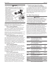
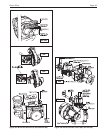
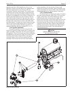
11.2.1 Burner
Check the burner for debris. Remove the blower
arm assembly to access the burner. Remove the 4 bolts
connecting the blower to the arm (see Figure 34).
Remove the 5 bolts, which hold the burner arm in place.
Pull burner up and out. Clean burner, if necessary, by
blowing compressed air from the outside of the burner
into the center of the burner, and wipe the inside of the
burner clean with glass cleaner. A dirty burner may be
an indication of improper combustion or dirty
combustion air. Determine the cause, and correct. If
damaged, replace the burner gasket when replacing the
burner.
NOTE: When installing the burner, make sure the
flange is aligned with the mating surface, as each is
keyed to control fit.
11.2.2 Modulating Gas Valve / Venturi
The modulating gas valve consists of a valve body
that incorporates the ON/OFF gas flow control and a
negative pressure regulator. It provides the air/gas ratio
control in combination with the venturi to the unit. It is
designed to operate with gas supply pressure between 4
and 13 inches w.c.. To remove the gas valve and or
venturi, shut off the 120 Volt power supply to the
boiler. Turn off all manual gas valves connecting the
boiler to the main gas supply line. Remove the front
door of the boiler to gain access to the gas valve and
venturi. Disconnect the four (4) flange bolts connecting
the gas manifold pipe to the gas valve. Remove the
electrical connections to the gas valve. Remove the bolts
connecting the venturi flange to the blower. This allows
the entire gas valve/venturi assembly to be removed as
an assembly to facilitate inspection and cleaning.
After the valve has been removed, reassemble in
reverse order making sure to include all gaskets and O-
rings. Turn on the manual gas valves and check for gas
leaks. Turn on the 120 Volt power. Place the unit in
operation following the instructions in Section10. Once
the boiler is operating check for leaks again and confirm
all fasteners are tight.
Check appliance setup according to Section 10.
11.2.3 Appliance Control
Brute Elite has an integrated control that
incorporates manual reset high limit control, operating
temperature control, modulating control, ignition
control, outdoor reset control, pump control and many
other features. If any of these features are thought to be
defective, please consult the factory for proper trouble
shooting practices prior to replacing the control. If
control replacement is required, turn off all power to the