


BRADFORD WHITE CORP.
Page 32
SECTION 7.
Electrical Connections
WARNING
The appliance must be electrically grounded in
accordance with the requirements of the authority
having jurisdiction or, in the absence of such
requirements, with the latest edition of the National
Electrical Code, ANSI/NFPA 70, in the U.S. and with
latest edition of CSA C22.1 Canadian Electrical Code,
Part 1, in Canada. Do not rely on the gas or water piping
to ground the metal parts of the boiler. Plastic pipe or
dielectric unions may isolate the boiler electrically.
Service and maintenance personnel, who work on or
around the boiler, may be standing on wet floors and
could be electrocuted by an ungrounded boiler.
Electrocution can result in severe injury or death.
Single pole switches, including those of safety
controls and protective devices must not be wired in a
grounded line.
All electrical connections are made on the terminal
blocks that are located inside the control panel.
NOTE: All internal electrical components have been
prewired. No attempt should be made to connect
electrical wires to any other location except the terminal
blocks.
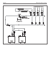
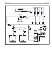
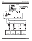
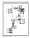
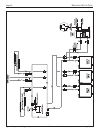
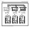
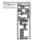
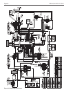
Wiring connections are shown in Figures 29 and 30.
Important Note: DO NOT MAKE/BREAK BRUTE
ELITE LINE VOLTAGE TO SIGNAL CALL FOR HEAT.
A “call for heat / end call for heat” MUST be connected
to the field interlock terminals. Some Brute Elite
components are designed to have constant voltage
during normal operation. If the Brute Elite's supply
voltage is toggled as a call for heat signal, premature
failure of these components may result.
Brute Elite does not recognize 4mA as a signal to shut
off. If the call for heat is not connected between the field
interlock terminals, Brute Elite will remain in low fire
when it sees 4mA as a modulating signal.
Caution
Brute Elite supply voltage must not be disengaged,
except for service or isolation, or unless otherwise
instructed by procedures outlined in this manual. To
signal a call for heat, use the 24V field-interlock, as
shown in the wiring diagram(s).
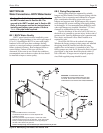
7.1 Main Power
Connect a 15A fused, 120-volt supply to the main
power switch (hot leg is connected directly to switch).
Neutral leg is connected directly to the white wire.
Ground wire can be connected to the grounding lug in
the control panel (see Table 11).
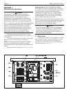
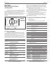
Figure 27. Control Panel Layout.