


Brute Elite
Page 11
SECTION 2.
Locating the Appliance
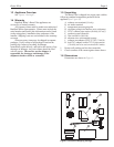
2.1 Locating the Appliance
Brute Elite is for indoor installations only.
The appliance should be located to provide
clearances on all sides for maintenance and inspection.
It should not be located in an area where leakage of any
connections will result in damage to the area adjacent to
the appliance or to lower floors of the structure.
When such a location is not available, it is
recommended that a suitable drain pan, adequately
drained, be installed under the appliance.
The appliance is design certified by CSA-
International for installation on combustible flooring; in
basements; in closets, utility rooms or alcoves. Brute
Elite Boilers must never be installed on carpeting.
The location for the appliance should be chosen with
regard to the vent pipe lengths and external plumbing
and on a level surface. The unit shall be installed such
that the gas ignition system components are protected
from water (dripping, spraying, rain, etc.) during
operation and service (circulator replacement, control
replacement, etc.). When vented vertically, the Brute
Elite must be located as close as practical to the vertical
section of the vent. If the vent terminal and/or
combustion air terminal terminate through a wall, and
there is potential for snow accumulation in the local
area, both terminals should be installed at an appropriate
level above grade or the maximum expected snow line.
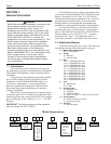
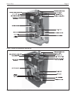
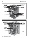
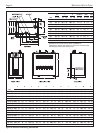
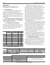
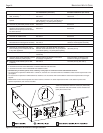
The dimensions and requirements that are shown
in Table 1 should be met when choosing the locations
for the appliance.
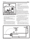
2.2 Locating Appliance for Correct Vent
Distance from Outside Wall or
Roof Termination
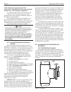
The forced draft combustion air blower in the
appliance has sufficient power to vent properly when
the guidelines in Table 2 are followed.
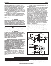
NOTE: When located on the same wall, the Brute Elite
combustion air intake terminal must be installed a
minimum of 12" below the exhaust terminal.Models 399-
850 also require a minimum horizontal distance from
intake to exhaust terminal of 36".
For concentric vent terminal kit (optional), follow
installation instructions included with the kit.
APPLIANCE
SUGGESTED SERVICE ACCESS CLEARANCE
SURFACE INCHES CM
Left Side 1 2.5
Right Side 12 31
Top 24 61
Back 6 15
Closet, Front (285-500) 6 15
Alcove, Front (285-500) 24 61
Front (600-850) 24 61
Vent – –
Certified by CSA for zero clearance to
combustible materials on all sides.
Table 1. Clearances.
INTAKE / EXHAUST
STANDARD MAX EQUIV. OPTIONAL MAX EQUIV.
SIZE VENT FT. M VENT FT. M
80 2" 40 6.1 3" 100 30.5
105 2" 40 6.1 3" 100 30.5
150 3" 100 30.5 n/a — —
199/210 3" 100 30.5 n/a — —
285 4" 100 30 n/a — —
399 4" 100 30 n/a — —
500 4" 100 30 n/a — —
600 4" 100 30 n/a — —
750 4" 40 6.1 6" 100 30
850 4" 40 6.1 6" 100 30
Installations in the U.S. require exhaust vent pipe that is a combination
of PVC & CPVC complying with ANSI/ASTM D1785 F441 or stainless
steel complying with UL1738. Installations in Canada require exhaust
vent pipe that is certified to ULC S636.
Intake (air) pipe must be PVC or CPVC that complies with ANSI/ASTM
D1785 F441, ABS that complies with ANSI/ASTM D1527 or
galvanized material.
Installer must comply fully with manufacturer's installation instructions,
including use of minimum exhaust length CPVC, to maintain ANSI
Z21.13 safety certification.
Closet and alcove installations do not allow the use of PVC under any
circumstances
To calculate max equivalent length, measure the linear feet of the
pipe, and add 5 feet (1.5m) for each elbow used.
Table 2. Vent / Air Pipe Sizes.