


Brute Elite
Page 33
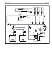
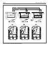
7.2 Pump Connections
Brute Elite energizes the pump contacts upon a
call for heat. Once the call for heat is satisfied the pump
will remain on for the defined pump overrun time.
NOTE: System and DHW contacts are dry contacts.
Appropriate voltage must be supplied to the System
and DHW pumps for proper operation. Boiler pump
contact (max 7.4 FLA) is fed by 120V (violet wire)
internally from main power feed.
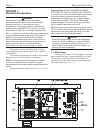
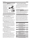
System pump connections are located on terminal
block 5 (TB5) in the control panel (see Figure 27). The
system pump contacts are rated for 120Vac, 7.4 amps.
To use the contacts, power must be supplied on one
terminal with the other terminal wired to the pump or a
relay controlling the pump.
DHW pump connections are located on terminal
block 5 (TB5) in the control panel and are rated for
120Vac, 7.4 amps. To use the contacts, power must be
supplied on one terminal, and the other terminal wired
to the pump or a relay controlling the pump.
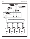
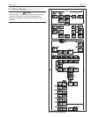
7.3 24Vac Transformer with Integral Circuit
Breaker
24Vac is supplied by a transformer mounted to the
backside or underneath the control panel, depending
upon the appliance. All 24Vac power is supplied
through a circuit breaker that is part of the transformer.
The transformer is then connected to terminal blocks 3
and 4 (TB3 and TB4).
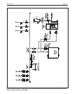
7.4 Hydronic Call for Heat
Connect the call for heat to terminal block 7
(TB7), connections labeled "T-T or interlock" in the
control panel.
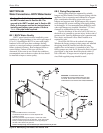
7.5 Outdoor Air Temperature Sensor
Connect the outdoor air temperature sensor to
terminal block 7 (TB7), connections labeled Outdoor temp
sensor. The outdoor air temperature sensor is used for
warm weather shutdown and outdoor reset.
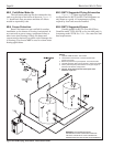
7.6 Domestic Hot Water Connection
Connect a DHW sensor or aquastat to terminal
block 6 (TB6), connections labeled DHW stat. The
aquastat or sensor will be automatically detected and
initiate the DHW call as needed.
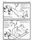
7.7 System Sensor (lead lag/cascading
operation only)
Connect the system sensor to terminal block 6
(TB6), connections labeled system sensor. Can be used
in a well for DHW tank applications with lead/lag.
7.8 External Control Connections
Connect 4-20mA signals from external controls or
building automation systems to terminal block 7 (TB7)
in the control panel. The connections are labeled
"Remote Anlaog Input". When making the connections
follow the polarity designations shown on the label.
7.9 Optional Field Connections
Terminal block 8 (TB8) in the control panel can be
used for connecting optional components, such as, low
water cutoffs, flow switches, additional high limits and
other field supplied devices that must be interlocked
with the boiler. All safeties or end switches must be
wired in series by removing the supplied jumpers.
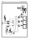
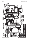
7.10 Lead Lag/ Cascading Wiring
Connections
Connect each boiler in the cascade system
together by daisy chaining each control from Modbus
port 1 (MB1) of the first boiler to the second and so on.
This can be done using 22awg or thicker shielded
twisted pair wire with drain. Two twisted pairs or three
conductors are needed.
a. To daisy-chain the boilers connect a wire from Modbus
port 1 (MB1) terminal A of the first boiler to Modbus
port 1 (MB1) terminal A of the second boiler.
b. If there are more boilers in the system connect a
wire from Modbus port 1 terminal A of boiler 2 to
Modbus port 1 terminal A of boiler 3.
c. Repeat these steps until all Modbus port1 terminal
A connections are wired.
d. Repeat the above steps for Modbus port 1 terminal
B and C connections to complete the wiring.
e. Connect the drain wire from the twisted pair wire
to ground on one end of the wire only.
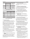
WATER HEATER
SIZES VOLTS PHASE AMPS
150-500
120 Single 2*
No pump
150-199
120 Single 7*
With pump
285-500
120 Single 8*
With pump
600-850 See Pump Rating Plate FLA
No pump (must be less than 7.4 FLA; 1HP or less)
*
Minimum 15A circuit required
Table 11. BNTV Electrical Data.
BOILER PUMP CONNECTIONS
RATINGS
SIZES VOLTS PHASE AMPS
(Boiler, System Pump and
DHW Pump Connections)
80–850
120 Single 2*
115V – Maximum 1HP
No Pump or 7.4A max
80-500
Less
With Pump
120 Single than
115V – Maximum 1HP
6*
or 7.4A max
*
Minimum 15A circuit required
Table 10. BNTH Electrical Data.