


BRADFORD WHITE CORP.
Page 48
11.2.6 Transformer with Integral Circuit
Breaker
The appliance has a 24Vac transformer with
integral 4 amp circuit breaker installed for supplying the
control voltage required for the appliance only. The
transformer is sized for the appliance load only and
should not be used to supply power to additional field
devices. If additional loads are added or a short occurs
during installation the integral circuit breaker may trip.
If this happens make sure to reset the circuit breaker
prior to replacing the transformer.
Depending upon the revision of the appliance the
transformer may be mounted to the back or underneath
the control panel. In either case, if the transformer must
be replaced turn off the 120Vac power to the appliance.
Remove the transformer wires from terminal blocks.
Remove the fasteners holding the transformer and
remove the transformer. Replace with a new transformer
in reverse order.
If the transformer is replaced with parts other than
the OEM transformer, be sure to add circuit protection if
it is not integral to the new transformer.
WARNING
Failure to include proper circuit protection may lead
to premature component failure, fire, injury or death.
11.2.7 Blower
The combustion air blower is a high-pressure
centrifugal blower with a variable speed motor. Speed
of the motor is determined by the control logic. 120
Volts remain on to the blower at all times. If a blower
change is required, turn off the 120 Volt power and gas
supply to the unit. Take the front panel off. Disconnect
the 120 Volt and control signal connections from the
blower. Disconnect the bolts connecting the venturi to
the blower housing. Disconnect the fan outlet bolts from
the burner door blower arm. If the fan is determined to
be defective replace the existing fan with a new one
reversing the steps above. Make sure to install all of the
required O-rings and gaskets between the blower arm
and the blower and blower face and venturi flange.
11.2.8 Heat Exchanger Coils
Black carbon soot buildup on the external surfaces
of the heat exchanger is caused by one or more of the
following; incomplete combustion, combustion air
problems, venting problems and heater short cycling.
Soot buildup or other debris on the heat exchanger may
restrict the flue passages.
If black carbon soot buildup on the heat exchanger
is suspected, disconnect electrical supply to the unit,
and turn off the gas supply by closing the manual gas
valve on the unit. Access the heat exchanger through the
burner door at the front of the boiler, and inspect the
tubing using a flashlight. If there is a buildup of black
carbon soot or other debris on the heat exchanger, clean
per the following:
Caution
Black carbon soot buildup on a dirty heat exchanger
can be ignited by a random spark or flame. To
prevent this from happening, dampen the soot
deposits with a wet brush or fine water spray before
servicing the heat exchanger.
1. Shut off the 120 Volt power supply to the boiler
2. Turn off all manual gas valves connecting the
boiler to the main gas supply line.
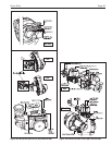
3. For NT 600 models only (all other sizes please
skip to step four). NT 600 models will require the
gas valve to be removed in order to remove the
burner door. To do this, remove the wire
connections from the gas valve. Remove the flange
bolts from the gas supply pipe connected to the gas
valve (1B). Remove the flange bolts connecting
the gas train to the venturi (1A). Remove the gas
train assembly keeping gaskets and o-rings.
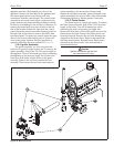
4. Remove the four bolts connecting the blower
flange to the burner door arm.
5. Remove the nuts located on the outside diameter
of the burner door to the heat exchanger.
6. Remove the burner door/burner assembly from the
heat exchanger.
7. Disconnect the condensate drain line.
8. Attach a longer hose to drain and run to a bucket.
9. Clean the heat exchanger by brushing light
accumulations of soot and debris. Use a brush with
soft bristle (non metal) to avoid damaging the
surface of the heat exchanger tubes.
10. Once the tubes have been brushed clean rinse the
tubes and combustion chamber with a small
amount of water to rinse all of the debris out of the
bottom of the flue collector and into the longer
condensate trap line, which is being diverted into a
separate container.
NOTE: The Warranty does not cover damage caused
by lack of required maintenance, lack of water flow,
or improper operating practices.
WARNING
Failure to rinse the debris from the heat exchanger
and temporary drain line may lead to clogged
condensate lines, traps and neutralizers. Condensate
pumps (if used) may also be damaged from the
debris left behind, possibly causing property damage.
11. Install all components removed in the reverse
order to place the appliance back in operation.
Make sure all gaskets are in place as components
are installed. Replace any damaged gaskets. Do
NOT reuse damaged gaskets.
12. Place the appliance in operation according to
Section 10 checking all gas connections for leaks.
Confirm all fasteners are tight.